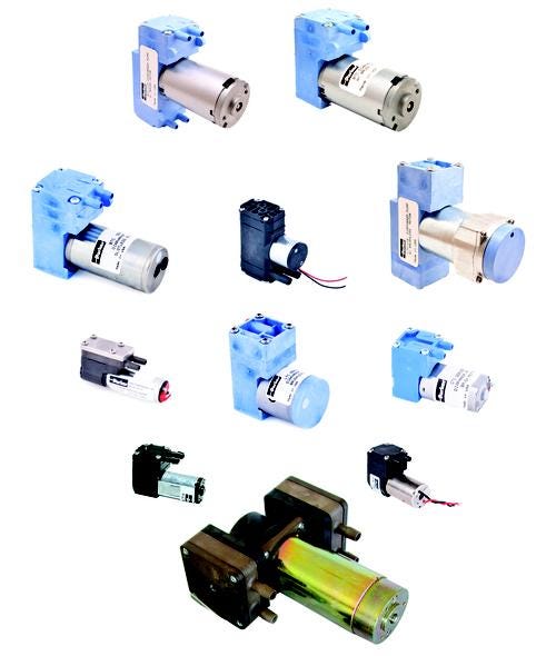
Optimizing Pump and Motor Design Is the Key to Machine Miniaturization
September 20, 2015

The trend toward miniaturization has become a challenge for machine designers faced with packing the same capabilities into smaller spaces. Medical device manufacturers, for example, continue to offer more portable devices, which forces design engineers to fit all the performance their customers demand into packages that take up less work space.
The struggle for size reduction also extends into larger instruments. According to a Parker Hannifin survey of lab equipment manufacturers and users, component miniaturization is key to helping them meet the demand for instruments that consume less laboratory space and fewer reagents and require smaller test samples. What’s more, these factors are critical to reducing the overall cost of ownership of an instrument, these respondents reported.
This size reduction trend is dependent on getting equipment design correct at the subcomponent level. Doing more with a smaller and more efficient pump is a common strategy that can provide OEMs with a sizable advantage.
Optimized pump design and how the pump is controlled can enable a compact footprint for the pneumatic circuit. This is often done by balancing high- and low-flow periods of operation to allow for a smaller pump. By achieving higher efficiencies by running the pump only at the level that matches demand, a smaller battery is possible.
This requires active control of the pump’s speed and flow and is commonly the dividing line between mechanical engineers and electrical engineers. Mechanical engineers responsible for designing the pneumatic elements tend to be challenged in terms of how to electrically control pump flow. However, when the mechanical and electrical disciplines are combined, often through applications engineers, the results can be impressive.

For example, an environmental monitoring device often requires a wide dynamic air flow range to sample the environments of work spaces both small and large. These devices must also be as portable as possible and offer a full day’s battery life. Proper dynamic control of a single pneumatic pump makes this possible, and increased efficiency can reduce battery size.
In in vitro diagnostic (IVD) instruments, a vacuum pump is often used in the waste circuit, and the load on this pump depends on the sample throughput rate of the instrument. By actively controlling the pump speed, a single smaller pump can maintain peak flow periods during waste removal and run at a slower, more efficient pace to maintain a vacuum reservoir in the system between these cycles.
READ MORE ARTICLES ON OPTIMIZING DESIGN:
Most innovative life science and medical device manufacturers are demanding more control over the pump-generated gas flow for improved patient therapies and more accurate patient monitoring. This flow rate flexibility is available in most diaphragm pumps, but utilization requires close attention and collaboration between OEM engineers and pump supplier applications engineers. Once the supplier properly configures the pump and motor, it is the responsibility of the OEM engineering team to control the pump properly. To integrate and control the pump correctly, the engineers must have a good understanding of motor and pump speed control methods.
Speed control is commonly used for all of the available Parker Precision Fluidics motor types, iron core permanent magnet direct current (PMDC) motor (often called brush motor, coreless brush motor, and brushless direct current (BLDC) motors.
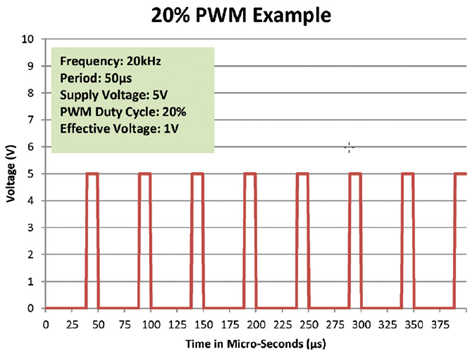
PMDC brush motors offer two methods for changing speed: pulse width modulation (PWM) or direct adjustment of the input voltage to the motor. Due to the cost and complexity of variable power supplies, direct adjustment of the voltage is not common; it is more typical for designers to use PWM to change the effective voltage to the motor.

Like brush motors, brushless motors can be controlled with direct input voltage adjustment or PWM of the input voltage, but because BLDC motors use an electronic controller to operate (which is built into some pumps), they offer more speed control options. Many BLDC motors can also be controlled independently of the input voltage, using a low current PWM signal or a low current 0–5 Vdc analog speed control.
The four most common methods for controlling the motor and pump speed are:
1. Input Voltage (brush or BLDC). Adjusting the voltage changes the speed of a motor proportionally. For example, the flow rate of a 12 Vdc pump can be reduced by operating the pump at 6 Vdc (depending on the application).
2. Input Voltage PWM (brush or BLDC). Similar to adjusting the voltage, the speed of the motor is reduced with a lower effective voltage. A lower voltage is simulated by turning off the fixed input voltage at a fast rate, often 20 kHz. The ratio of on-time to off-time (duty cycle) defines the effective voltage applied to the motor.
3. External PWM (BLDC only). The input voltage on the first two wires of the motor is fixed and does not change; the speed is adjusted by applying a PWM signal to a third wire. A low current signal is externally switched to ground at a high frequency (by the system controller). The internal BLDC motor controller responds to this signal to reduce the speed proportionally to the signal duty cycle.
4. 0–5 Vdc Analog Speed Input (BLDC only). The input voltage on the first two wires of the motor is fixed and does not change; the speed is adjusted using an externally supplied DC voltage applied to the third wire. The internal BLDC motor controller responds to this signal to reduce the speed linearly with the input voltage. For example, 5 Vdc could be at 100% speed, 2.5 Vdc is 50% speed, and at 0 Vdc the motor would be off.

Jamie Campbell is a Division Applications Engineer for the EMEA region at the Precision Fluidics Division of Parker Hannifin Co. He has been with Parker Hannifin for five years. He earned his Bachelor’s of Science in Computer Engineering at the University of North Carolina–Charlotte and his Master’s of Business Administration from East Carolina University.
About the Author(s)
You May Also Like


