5 Best Practices for Optimizing Vehicle Connectivity
These tips can help ensure vehicles are capable of high-speed C-V2X communications for a number of safety functions.

At a Glance
- Learn what a link budget is and how to manage it.
- Choose the right antenna placement.
- Understand your options for cables, interconnects, and compensators.
With each passing year, consumers have higher expectations for wireless connectivity from their vehicles—and design engineers are at the forefront of creating systems to meet these expectations. Wireless connectivity and related applications come in different forms, ranging from elaborate infotainment systems to vehicle control features such as route planning, navigation, and identification of hazards.
For control and road safety, vehicles of tomorrow will be able to communicate using vehicle-to-everything (V2X) systems. “Everything” can include a cellular network, roadside infrastructure, individual vehicles, bicyclists, and pedestrians. Cellular V2X (C-V2X) is a standard for V2X defined by the international cellular communication standards group 3GPP.
C-V2X can utilize either vehicle-to-network (V2N) communications via cellular networks or it can use direct communication, known as PC5. PC5-based direct communication functions, which are similar to a walkie-talkie, permit the vehicle to communicate with other vehicles or nearby devices without an intermediary. This capability addresses one of the shortcomings of V2N, which requires cell network coverage, and many suffer from long latency because the signal is sent through multiple stages (device to cell tower, cell tower to internet, internet to second cell tower, and cell tower to second device). This also can be too time-consuming to provide critical data in a timely manner.
PC5 communications is optimized for close communication, within 1.5 km and line of sight, since users in this range are most relevant to the safe operation of the vehicle. Longer-range communications can be managed by V2N devices and the cellular network. The rapid rise of automated driver assistance systems (ADAS) and safety functions is fueling demand for faster and more reliable PC5-based connectivity. With some safety and regulatory organizations considering requiring PC5 communication to achieve a 5-star safety rating, PC5 is evolving from a nice-to-have to a must-have feature. As a result, vehicle designs must incorporate antennas and supporting architecture that deliver dependable V2X connectivity via PC5.
Automotive engineers must address challenges and potential pitfalls for antenna systems early in the design process. Optimizing performance of the antenna system entails maintaining excellent signal integrity by minimizing energy loss, or signal attenuation, both outside and inside the vehicle. Here are five tips system designers can apply to help ensure vehicles are capable of high-speed C-V2X communications required for a range of safety functions.
Tip #1: Know Your Link Budget

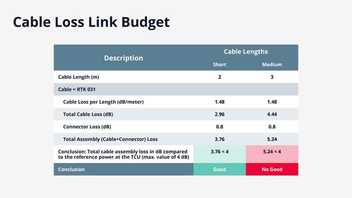
An example of a Cable Loss Link Budget. MOLEX
Designing the antenna system for optimal performance is a complex process, and the first step should be mapping out a link budget. The link budget predicts how much energy is lost between the transmitter in Vehicle A and the receiver in Vehicle B (and vice versa for the return message). At 5.9 GHz, the frequency used for PC5-based vehicle-to-vehicle (V2V) communications, energy loss can be more significant than at lower frequencies, making it even more critical to establish the link budget before any further steps in design are taken.
When establishing the link budget, designers must consider energy loss within the antenna block; within the cable block, including any required connectors; and in the telematic control unit block. Mapping this information is vital to designing the system to counteract any excessive energy loss. As design work proceeds, the antenna system design can be refined as necessary to maintain an acceptable level of signal attenuation and ensure reliable and effective operation of the TCU.
Tip #2: Maximize Signal Strength with Proper Antenna Placement

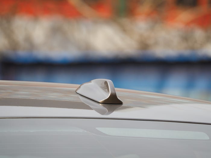
KOOL99/ISTOCK/GETTY IMAGES PLUS VIA GETTY IMAGES
Before designers can lay out the vehicle antenna system, optimal, effective antenna placement needs to be determined. Physical placement of the antennas on the vehicle has a major effect on signal strength. At the same time, the choice of location for the antennas must be balanced against the overall design and aesthetics of the vehicle.
When evaluating placement, the style (e.g., shark fin or blade) and location (e.g., front windshield or bumper) of the antenna are major considerations. Location will affect multidirectional connectivity, with signal strength varying significantly by direction depending on the antenna location. For example, shark fins are placed on the vehicle roof, ideally at the highest point. This offers the potential for 360-degree coverage around the vehicle. But customized shark fins frequently contain many internal antenna elements, such as 5G cellular, high-precision GNSS, Wi-Fi, or AM/FM, that can block the signal and degrade performance. Counterintuitively, glass roofs are especially detrimental to antenna performance at 5.9 GHz. As a result, PC5 elements are frequently added to the back of the shark fin and are focused on rear-facing performance.
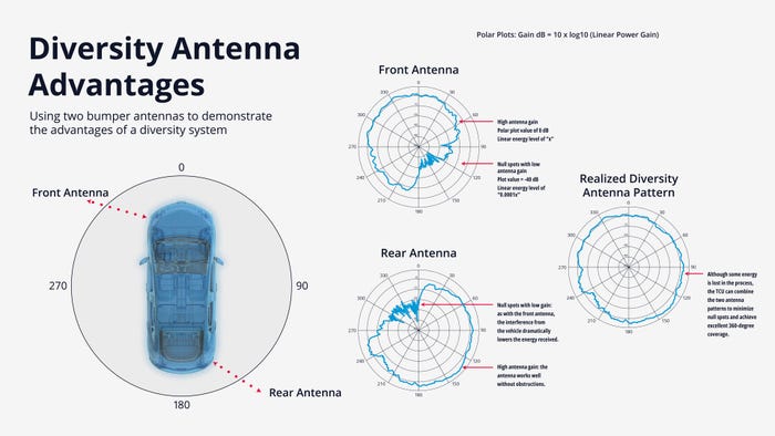
Antennas placed in the windshield or within the bumper will have their performance affected by nearby devices and structural materials. For an antenna at the front left corner of the vehicle in the bumper, there are likely to be “blind spots” to the right and rear because any signal would need to pass through a significant portion of the vehicle’s structure, thereby dramatically reducing the signal strength. Polar plots are used to visualize blind spots by identifying directions with poor signal strength. With this information, the antenna style or location can be revised to improve connectivity.

A diversity system for antennas offers advantages. MOLEX
In many cases, optimizing signal strength can be accomplished by using two antennas that complement each other’s coverage (assuming the TCU accommodates two antennas). With an antenna at the front and a second at the rear, or with antennas at opposite corners, each antenna maintains the best signal strength in the direction of the other’s blind spot. This is called a diversity system. Using polar plots of signal strength, antenna placement can be intentionally designed to maximize signal strength and improve the speed and reliability of the vehicle’s PC5 connection.
Tip #3: Optimize Your Cables and Interconnects
Once the antenna locations and TCU are determined, the next step in the design process focuses on routing cables and selecting interconnect options to optimize system performance. A significant source of signal attenuation can be cable loss. This is primarily affected by the cable’s type and length as well as the connectors utilized. Cable loss can be controlled, however, but designing for optimal signal strength requires a range of factors to be considered. These factors include vehicle architecture as well as cost, weight, and component manufacturability.

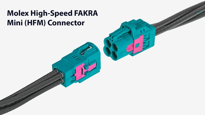
The high-speed FAKRA Mini connector. MOLEX
Shorter cable runs and high-performance 50-Ohm coax cables can help reduce cable loss. With more efficient cables, though, come trade-offs in cost and weight. High-performance wire is heavier, adding weight to the vehicle, and more expensive. It can also be more difficult and time-consuming to install. For these reasons, cable lengths should be kept as short as possible, but this must be evaluated alongside antenna placement demands as well as the overall vehicle architecture and wiring harness. Electrical connectors can also make a major difference in overall system performance, both in managing cable loss and ensuring reliable performance. High-performance, automotive-grade connectors, such as Molex High-Speed FAKRA Mini (HFM) Connectors, also can help reduce cable loss.
As with many design decisions, optimizing intra-vehicle connectivity while limiting cable loss is a balancing act between meeting system performance goals with limiting cost and weight. The link budget serves as a key factor in managing these priorities.
Tip #4: Incorporate a Compensator, If Needed
In many vehicles, particularly those utilizing two antennas, longer cable runs will be necessary. On cables that run over two meters, signal attenuation is a significant gating factor to top performance, typically pointing to the need for a bi-directional amplifier, or compensator. The compensator can improve performance by boosting signal strength in transmit mode to offset energy loss in the system. In receive mode, the compensator locks in the signal-to-noise ratio. The link budget will highlight the need for a compensator for longer cable runs that are all too often included in today’s systems.
The compensator should also be agnostic, meaning it will work with different system protocols from major PC5 chipset providers, although customers will frequently customize functionality. For the typical antenna system, an automotive-grade, protocol-agnostic compensator, such as the Molex V2X Compensator, offers several advantages. It incorporates a PC5 antenna element; offers a high degree of design flexibility, including different gain control settings for inbound and outbound signals; and its rugged design helps ensure reliable system operation.
Tip #5: Thoroughly Test the System at Every Stage
Throughout the design process, it is vital to test the vehicle antenna system repeatedly, both on a component basis and as a complete system. Ensuring the system and its components work as designed is critical to avoiding surprises when the design is finalized.
Early in the design process, simulation testing is necessary. Utilizing calculations derived from simulating the signal attenuation of each component in the system is essential in creating the link budget. Then, as the design is refined, simulation testing can be revised as needed. Once the design is in the prototype phase, a testing facility should be used to provide a full range of data on the operation of the complete system. Molex leverages advanced, dedicated testing facilities in Europe and North America to determine the performance of the system in a wide range of conditions. Using this information to validate simulations and the link budget will help ensure the antenna system works as required.
The Increasing Importance of Connectivity
As safety systems in vehicles begin to rely more increasingly on PC5-based C-V2X connectivity, it will become increasingly vital for automotive designers to ensure that vehicles can maintain reliable cellular connections with nearby vehicles and other devices. Consumers and regulatory bodies will require vehicles to achieve high standards for connectivity to meet safety expectations.
To accomplish this, it is necessary to design vehicle antenna systems from the start with considerations for signal attenuation challenges. Taking these steps and optimizing end-to-end operation of the antenna system as the vehicle design progresses will significantly improve connectivity and overall system operation to deliver performance that meets consumer demand. This, in turn, will improve customer satisfaction and enable connected vehicles of tomorrow to deliver the desired levels of performance, comfort and efficiency, most importantly, with the highest levels of driver and passenger safety.
Interested in learning more? Suggested reading: SAE specification J3161
About the Author(s)
You May Also Like


