How to Turn an Old Rotary Phone into a Numeric Keypad
Updating a 1951 vintage Western Electric makes data entry possible thanks to the mechanical analog-to-digital converter.
April 8, 2024

At a Glance
- Project entails putting an ESP32 system-on-chip (SoC) module into the phone
- Unexpected Maker TinyS3 and CircuitPython with the Adafruit CircuitPython library bundle are also used
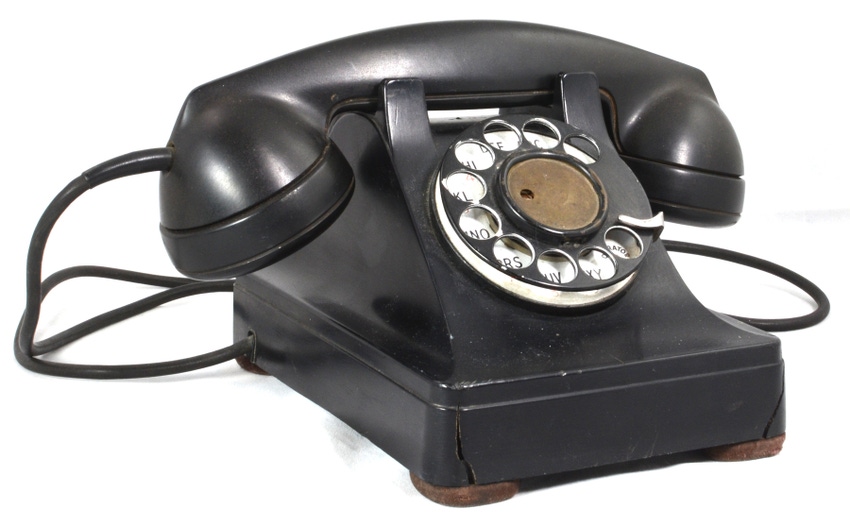
Retro technology is “in” these days. Vinyl records, print books, and even film photography have all made a comeback. And “renew, reuse, and recycle” is a trend that recognizes the value and aesthetic of older devices. In keeping with that concept, I have in my possession a 1951 vintage Western Electric model 302 rotary dial telephone that I’m giving new life to.
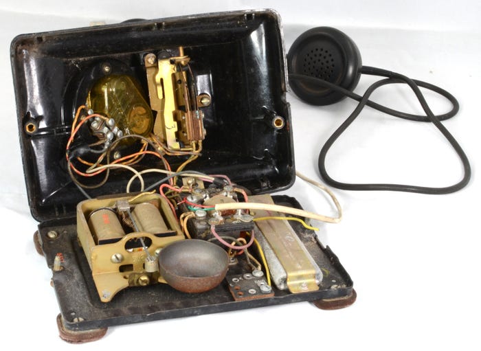
The phone “brain” is a sort of circuit, but not of the type familiar to us present-day electron jockeys. It is essentially an analog computer that converts stepped rotational motion into digital data. It is a mechanical analog-to-digital processor.
Amazingly, before I dug into it and disconnected the internal wiring, the phone was still 100% operational. All it needed was an analog POTS (plain old telephone service) landline. While all long-distance phone transmission and most local traffic is digital these days, the phone system can still provide analog POTS landlines from a local exchange to households. These POTS lines are still fully compatible with equipment that’s nearly 100 years old. I don’t have such a line into my house, but if I did, I could plug the unit in and make and receive calls.

Inside the telephone. DUANE BENSON
Giving an Old Phone a New Purpose
I’d like to make use of the phone as more than a desktop conversation piece. To that end, I’ve put an ESP32 system-on-chip (SoC) module into the phone. The ESP32 reads the numbers from the dialing action and sends them on to my computer as an HID (human interface device). In other words, I’ve turned it into a numeric keypad.
As the phone sits idle with the handset in its cradle (called being “on hook”), the phone is effectively disconnected from the phone line by the hook switch in the cradle. The line from the local telephone exchange is charged with a DC voltage of around 48 volts, capable of providing no more than about 100 mA. When the handset is picked up (called being “off hook”), the normally closed (NC) cradle switches close and a current loop is created between the phone and the local phone exchange. At this point, the DC current loop is active and an analog tone, called a dial tone, is modulated onto the line at the exchange.
The phone is dialed (yes, this is where the term “dial a phone” comes from) by placing a finger in one of the numbered holes on the dial, rotating the dial to the end point, and releasing the dial. As the spring-loaded dial rotates back to its home position, it passes an interrupter switch that breaks the current loop for about 40 ms. The current loop passes the interrupter once for each count of the chose digit. The break is approximately 60 ms between breaks. The timing is regulated by the mechanical clock spring that spins the dial back to its home position.
If you turn it to the number 3, for example, it will spin back to its home position and break the current loop three times, once for each number it passes. Zero (0) is in the last spot and gets ten pulses. That means that in an analog rotary phone system, numbers one through ten are represented, but the MSB for ten is essentially stripped off to turn it into a zero.

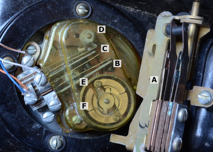
A: Hook switch, B: Dial in use switch, C: Digit pulse switch, D: Cam to engage/disengage digit pulse switch, E: Cam (behind switch bar) to control dial in use switch, F: Dial return spring. DUANE BENSON
The electric circuitry is primitive, to say the least. It consists of a transformer, two capacitors (combined into a single lead container), an electromagnetic bell, the hook switch, and the dial switch.
The switches are a set of mechanical relays, with the rotary dial switch being quite elaborate. The hook switch (A, above) is a double-pole, single-throw switch. Both switches are open when the handset is in the phone cradle, referred to as being on hook, and closed when the handset has been picked up, off hook.
The dial setup is much more elaborate. It has multiple switches controlled by a set of cams (D and E). One of the switches (B) is normally open, but closed when the dial is anywhere other than the home position. The other switch (C) is a double throw such that one is normally open and the other normally closed. The flip states once for each digit passed as the dial rotates from maximum to home. This switch generates the pulses that I count. I use the normally closed half and count pulses that transition from high to low.
The ESP32 Circuit
Before going further, you might want to download code from my GitHub site. The software is written in Adafruit CircuitPython, version 8.X. You can find it on my Github page.
For my setup, I use the hook switch (A) as my “sleep” vs. “awake” switch. I don’t use the ESP32 sleep mode in this incarnation. It’s a USB wired connection, so I don’t need to worry about conserving battery power. I may at some point turn this into a Bluetooth device and then a real sleep mode will be important. For now, I just wait in a “sleep” loop until the handset is picked up. Switch A is closed while on hook and open while off hook, so my while loop waits while not off hook.
Once off hook, I wait in a second while loop until the dial action is taken. Within the code, I ignore everything unless switch B has closed. Switch B is normally open and closed when dialing. It’s closed in the photo above because dialing is in progress.
When switch B is closed, I count any changes in the state of switch C. C is double pole, so I monitor the closed side and count a negative, or “off” pulse. It’s important to note that after reading any of the switches, I pause for 5 milliseconds to account for switch bounce.
Once switch B is open again, I know that dialing is done, so I have my digit. I add 0x1d (29 decimal) to the number. That’s the offset to get to one (1) in the standard HID keyboard code. The phone uses 10 pulses to represent zero (0) and, conveniently, so does the HID keyboard code.
Parts List for Turning an Old Rotary Phone into a Numeric Keypad
1950’s vintage Western Electric model 302 rotary phone (one that’s degraded enough to not be of historical value)
Unexpected Maker TinyS3
CircuitPython with the Adafruit CircuitPython library bundle

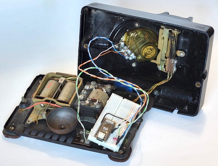
ESP32 in protoboard, wired to dial. DUANE BENSON
Wiring It Up
I only need three wire pairs to the ESP32. I also put a 0.01 uF ceramic capacitor on the ESP32 power rail to help combat noise. Switch A is connected with the solid green wire, as seen in the photo above, to the ESP32 +3.3 V bus and the white/green wire to ESP32 pin IO3. Switch B is connected with solid blue to the ESP32 +3.3 V bus and white/blue the ESP32 pin IO4. Switch C is connected with the solid orange wire to the ESP32 +3.3 V bus and white/orange to ESP32 pin IO5. Now, plug the phone into a USB port or hub, pick up the handset, and dial a number. The computer sees it as a number coming from a standard keyboard. That’s all there is to it.
What’s Next for the Project
At some point I want to turn this into a Bluetooth HID device. Unfortunately, CircuitPython doesn’t yet fully support the ESP32 Bluetooth in the TinyS3 board. I have to wait a bit for that support or change either the language I use or the board variety. Most ESP32s can run CircuitPython, MicroPython, or Arduino code. You can also develop in native C. I just need to find some combination with good Bluetooth support. I don’t anticipate more than about an hour being necessary to update the code. At that point, I will need a proper deep sleep mode for the microcontroller. It should otherwise be the same in operation.
About the Author(s)
You May Also Like


