December 28, 2012

The MEMS gyroscope has impacted so much of our everyday lives, in particular in consumer electronics, that engineers now design systems with this as an essential component.
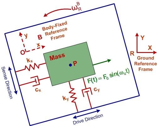
In the age of model-based design, knowing how this device works and how to model it are essential. This is not the bulky, spinning-disk gyroscope we see in science museums. A gyroscope is a device that measures the angular velocity of a body about a specified axis of rotation. The figure shows a physical model of a typical MEMS vibratory gyroscope designed to measure the angular velocity of the body about the Z-axis of the ground reference frame.

The main principle of MEMS gyroscopes is the transfer of energy between two modes of vibration, the drive and the sense modes, through the Coriolis acceleration. How does this happen and what are the challenges? Developing a mathematical model for this physical model will answer our questions; every engineer needs to be able to do this.
It all starts with a fundamental kinematic relationship specifying the absolute acceleration of the mass translating in the body, whose rotation rate we want to know. This is shown below with a matrix relationship between the ground and body-fixed reference frames, here assumed to have a common origin.

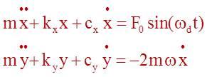
We next apply Newton's 2nd Law to the mass in both the x and y directions, resulting in two coupled differential equations of motion, shown below, where F₀sin(ωdt) is the driving force. Note the Coriolis acceleration terms: 2ωx and 2ωy.

Assume a constant angular speed ω and, since ω is usually much smaller than the natural frequencies of the system, neglect terms involving ω 2. Since the sense-mode response y is much smaller than the drive-mode motion x, the term 2ωy can be dropped. The resulting equations are:

The first equation can be solved independently. Its solution can then be substituted into the second equation, which can be solved for the sense-mode response y. The resulting amplitudes of motion X and Y are given below; Y/ω is called the gyroscope sensitivity.

The sensitivity is proportional to the oscillating mass, which puts some restrictions on the level of miniaturization that can be achieved. To achieve maximum sensitivity, resonance in both modes is desirable, i.e., ωd = ωx = ωy. The expression for the gyroscope sensitivity then becomes:

Qx and Qy are called the quality factors of the drive and sense modes, respectively, and high-quality factors are desirable to improve sensitivity.
This type of work should be considered fundamental for all engineers; it is what differentiates model-based design engineers in the 21st century.
Related posts:
About the Author(s)
You May Also Like


