Sign up for the Design News Daily newsletter.
OEMs must often decide which is the best control style for their application. The following detailed descriptions will assist with properly integrating the motor speed control with whichever option is chosen.
February 15, 2016
6 Min Read
.svg?width=850&auto=webp&quality=95&format=jpg&disable=upscale "How to Properly Integrate Motor Speed Control for Brush and BLDC Motors")
In my previous article, I described the four most common methods for motor and pump control: input voltage, input voltage pulse-width modulation (PWM), external PWM, and 0–5V DC analog speed input. Although external PWM control is preferable when speed control is required, OEMs must decide the best control style for their application. The following detailed descriptions will assist with properly integrating the motor speed control with whichever option is chosen.
Input Voltage PWM (brush or BLDC)
This technique, often referred to as “2-wire” PWM, is one of the simplest methods for controlling pump speed in a device. The PWM signal is often generated from a microcontroller and a power transistor. The input voltage to the motor is turned on and off at a high frequency so that the average power to the motor is reduced. The following image illustrates an example of a “low side” PWM driver, where the ground to the motor is being switched by the “customer printed circuit board assembly” to reduce the speed.
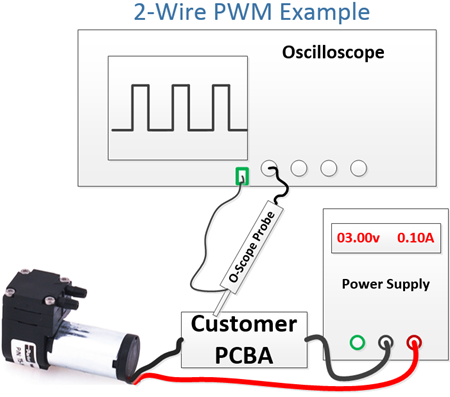
For brush motors, 2-wire PWM is the most common method for control, and it is very effective. It is similarly effective with brushless DC (BLDC) motors, but it does present some limitations. Many BLDC motors have an internal controller that must maintain a minimum voltage to operate properly. When applying a PWM cycle to the input voltage, it is also reducing the effective voltage to the controller electronics; this limits the available speed control range. Using an external PWM control can provide more range in this situation.
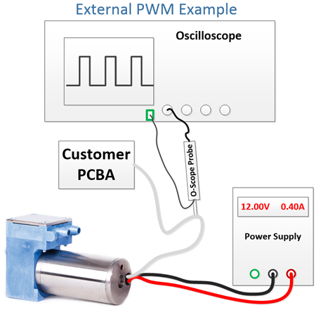
External PWM (BLDC only)
This is the recommended method for controlling the speed of a BLDC diaphragm pump. This method provides the most dynamic control of a pump and can simplify the engineer’s electrical circuit in some cases because only a low-current transistor is required for the switching signal.
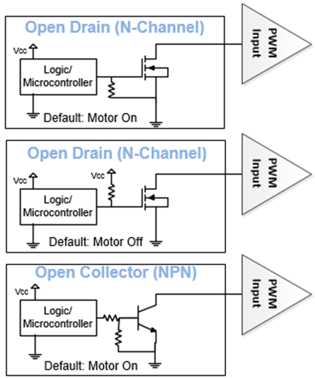
Most diaphragm pumps with external PWM require an “open-drain” or “open-collector” circuit on the OEM engineer’s device PCBA to provide the PWM signal. The BLDC motors have an internal pull-up resistor so the open-drain or open-collector circuits will actively bring this voltage to ground for the low part of the PWM signal. The following illustrations show examples of recommended circuits.
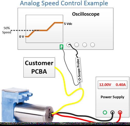
0–5V DC Analog Speed Input (BLDC only)
In some applications, a PWM signal is not feasible or is not preferred by the system designer. Many BLDC motors offer an external analog DC signal input. In this case, the motor is provided a direct voltage to operate, but a separate low current 0 to 5V DC input (yellow wire) controls the speed of the pump.
The actual control voltage range may vary depending on the motor, but the concept is the same: a 0V DC signal would disable the motor, 5V DC would represent full speed, and the range between 0 and 5V DC would adjust the speed of the pump.
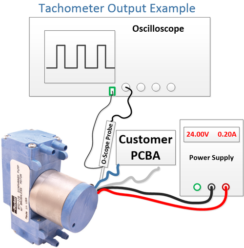
Speed Monitoring -- Tachometer
Many BLDC motors also have the ability to output a tachometer signal so the engineer’s device can monitor the actual pump speed. The signal is a digital pulse that can be used to determine the speed of the pump. This is useful in applications where the pump will need to operate very slowly; with this information, the device controller could increase the speed if the pump begins to stall (that is, pump speed approaches zero). It also provides additional safety and/or diagnostics feedback for confirming proper system function.
Design Challenges: Control Input Vs. Speed
The speed control signal to the motor can reduce or increase flow, but it is not a linear relationship. For example, at a fixed 50% PWM signal, the speed of the pump will be reduced but not by exactly 50%. Also, as the load on the pump changes, the speed of the pump will also change, even while the PWM signal is fixed.
READ MORE ARTICLES ABOUT MOTOR CONTROL:
The maximum motor speed can be reduced by the pump configuration or the pressure/vacuum load on the pump in the application. Torque and speed have a linear relationship; when more torque is required to turn the pump, the motor will slow down.
Motor Stall
Pump motors may be damaged if the pump stalls. When the motor’s rotor is locked in this position and power is being supplied to the motor, heat will increase and can damage the internal controller. When using speed control to reduce speed, a motor stall is more likely and should be closely monitored.
It is recommended that system designers implement a safety current limit or fuse to power the pump. This can help prevent damage to the pump motor and system if a stall event occurs.
Restart With Reduced Speed
Using any speed control method reduces the effective power to the motor. If the speed is reduced during restart, the starting torque will be reduced. Designers must ensure that the pump is capable of restarting under all conditions (such as pressure load and environmental temperature) when the speed is reduced.
Recommended Frequency
When using a PWM speed control method, the recommended frequency is 20 kHz. Frequencies lower than 20 kHz may create an audible buzzing sound, as the audible frequency range for humans is 20 Hz to 20 kHz. Using higher frequencies can limit the control range because of transistor rise and fall time; it is possible to switch so quickly that a low- or high-duty cycle signal appears as 0% or 100% because the transistor cannot switch fast enough. Also, with some motors and control circuits, PWM frequencies greater than 20 kHz can reduce efficiency.
Summary
In an era when engineering staffs are shrinking as much and as quickly as the instruments they design, it helps to work with multifaceted and experienced component suppliers. For example, Parker is a pump supplier that builds most of its own brushless motors. This expertise in both motor and pump design speeds customization and prototype production, which can help shrink engineering timeframes and costs.
Jamie Campbell is a division applications engineer for the EMEA region at the Precision Fluidics Division of Parker Hannifin Co. He has been with Parker Hannifin for five years. He earned his Bachelor’s of Science in Computer Engineering at the University of North Carolina–Charlotte and his Master’s of Business Administration from East Carolina University.

You May Also Like
Editors' Choice


Jun 4 - Jun 6, 2024
Jun 4 - Jun 6, 2024
Innovation in automation starts here. Discover and collaborate on automation solutions that are revolutionizing the entire production lifecycle — from design to production to market — and sharpen your competitive edge. ATX South is part of IME South, a six-in-one expo offering the latest insights & solutions spanning medtech, packaging, automation, plastics, design, & processing.
Register Now