Sign up for the Design News Daily newsletter.
Particularly challenging, blind keyhole welding meant a lot of trial and error with repeated physical experiments using expensive alloys and high-value component parts, thus necessitating simulation of complete keyhole physics.
January 25, 2016
3 Min Read
.svg?width=850&auto=webp&quality=95&format=jpg&disable=upscale "Simulation of Laser Welding Shortens Design Cycle and Optimizes Component Design at Owens Corning")
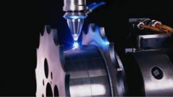
Byron Bemis, senior research associate at Owens Corning, and his team were asked to design a new generation of components that could be made through laser welding. In fact, with this particular R&D project, Bemis and crew were breaking new ground at Owens Corning’s Science and Technology Center in Granville, Ohio. To design and fabricate the parts, their initial designs called for blind keyhole welding through one sheetmetal part and into another.
“Developing the welding parameters to make those welds work reliably and robustly took a lot of trial and error,” Bemis said. “To accomplish this using physical prototypes meant fabricating the individual component parts and then laser welding them up, using a set of pre-determined parameters to see what happens.”
Bemis added that one of the most challenging aspects of this project was the necessity to weld near small features, near corners, and edges. If the laser is running too hot or moving too slowly, the feature or edge could melt, ruining the part.
(Source: CD-adapco)
These welds varied in size from millimeter- to submillimeter-scale, made on very small parts that demanded high-precision fabrication. Bemis had to run narrow weld beams -- 50-micron weld spots using up to a kilowatt of laser power on an individual spot. The materials used were alloys with high melting points, molten metal viscosity, and surface tension, which made for some interesting non-standard welding physics.
Complex geometries were also involved, including small features, edges, and circular sections. Because deep penetration was necessary to make the part, the keyhole mode welding technique was required, in which the laser penetrates completely through a workpiece, forming a hole at the leading edge of the molten weld metal. As the laser progresses, the molten metal fills in behind the hole to form the weld bead.
[Learn more design hardware & software trends and developments at Pacific Design & Manufacturing, Feb. 9-11, at the Anaheim Convention Center.]
All of these considerations -- in particular, the blind keyhole welding -- meant a lot of trial and error. Running hundreds of repeated physical experiments using expensive alloys and high-value component parts was prohibitive, thus necessitating simulation of complete keyhole physics and which could adequately predict quantities of interest, such as weld pool diameter and zone shape as well as penetration depth in order to specify the optimal laser process parameters.
Bemis eventually used CD-adapco’s Star-CCM+ to simulate the welding heat transfer process, predicting both the weld width and the behavior of features affected by the blind welding. Bemis commented that the computational fluid dynamics (CFD) simulation software has the ability to simulate the welding process and provide insight into the thermal transient experienced during welding in a manner that is both practical and fast enough for industrial use.
For the past 30 years, engineers trying to perform CFD simulations struggled with the interaction between multiple moving objects. Traditionally, this required the generation of an interconnected mesh between the objects, an intensive manual process that was extremely difficult and time consuming. In fact, it was almost impossible to do if extreme ranges of motion or close interaction between objects were involved.
Overset meshing -- sometimes called “overlapping” or “chimera” mesh –- is an approach to handling the modeling and simulation of the complex physics associated with moving objects by generating an individual mesh around each moving object, which can then be moved at will over a background mesh.
You May Also Like
Editors' Choice


Jun 4 - Jun 6, 2024
Jun 4 - Jun 6, 2024
Innovation in automation starts here. Discover and collaborate on automation solutions that are revolutionizing the entire production lifecycle — from design to production to market — and sharpen your competitive edge. ATX South is part of IME South, a six-in-one expo offering the latest insights & solutions spanning medtech, packaging, automation, plastics, design, & processing.
Register Now