Sign up for the Design News Daily newsletter.
This is the first part of a two-part series that looks at the material science of cold forming.
March 18, 2016
3 Min Read
.svg?width=850&auto=webp&quality=95&format=jpg&disable=upscale "The Cold Forming Value Chain in Micro/Miniature Component Design - Part 1")
New product design engineers rely heavily on design and manufacturing techniques learned through education, repeated application, and empirical success. Many alternate techniques are often approached with caution, particularly on mission-critical applications where a known solution is proven, and thus considered “safe.”
In spite of its relatively low visibility, there is a time-tested manufacturing technique that is not well understood, and therefore is not being fully utilized to achieve cost, quality, yield, and waste reduction objectives that manufacturers seek to improve quality and reduce cost. That technique is cold forming.
Cold forming is not a new technology for manufacturing micro-precision components, yet it is still not well known or understood among New Product Development (NPD) teams. One of the reasons for this is a widespread lack of related course work in engineering schools. Here, we will provide a fundamental description of the cold forming process, discuss its features and benefits, and review some of the advantages over alternate manufacturing methods such as machining, MIM, and stamping.
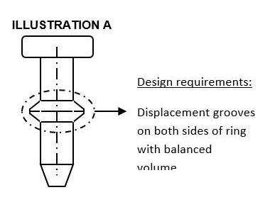
Shown is an example of a part often submitted for a roll-forming quote. The designer in this instance has not taken into account “where is the material for the annular ring coming from?”
(Source: Sussex Wire)
Successful application of cold forming depends inherently on each project’s four key contributors: the component manufacturer; the materials provider; the tooling designer/manufacturer; and finally, the machinery manufacturer. Each plays an important role in determining how a part design can be executed most effectively and provides feedback to the customer regarding critical dimensions, tolerances, potential limitations, and alternatives to improve strength and reduce cost while achieving all functional objectives.
New product design engineers are well advised to explore these strengths and limitations early in the design process, and to engage in a consultative relationship with the component design and manufacturing firm to collaborate on modifications that may well improve the component’s strength and facilitate its manufacturability, while at the same time, providing the lowest cost option available.
All too often, by the time a micro/miniature part geometry is fixed by the NPD engineer, the opportunity for making improvements has passed. Even though these parts might play a small role in the greater project, their designs can be streamlined to meet all the designer’s objectives if known ahead. In other words, trade-offs can sometimes be made on non-critical dimensions & tolerances in order to meet functional specifications, especially if the designer and component manufacturer are working together before the final part design is approved. In fact, this collaborative approach works for any manufacturing technique, not just cold heading or roll forming.
What Is Cold Forming?
Cold forming is the application of force with a punch to a metal blank staged in a die. The force exceeds the alloy’s elastic limit, causing plastic flow until the metal blank assumes the shape bound by the punch and the die. As the name implies, this method of forming is achieved by force alone, forgoing the application of additional heat or cutting and shearing. Consequently, cold forming does not re-anneal or mechanically damage the material’s original metallurgical grain structure like other processes can.
There are four principal advantages to cold forming:
Reduced scrap/cost
Cold forming is a net shape solution. During the process, wire is transformed by a sequence of die blows into a specific shape, with the material flowing to fill the part geometry and dimensional tolerances defined by the tooling engineer. So there is virtually no waste created. Without scrap to deal with, there is little to no recycling cost associated with the process, less lubricant to reclaim, and minimal labor to handle it all. In general, the wire feedstock is less expensive than the bar used for machining. Because sizing can be done in line with the heading operation, the tolerances on the wire feedstock do not need to be as tight as those demanded for the Escomatic Quality wire feedstock.
With all forms of screw machining, including single- and multi-spindle and Escomatic processes, scrap is not only unavoidable, it is a significant by-product of the process, often equivalent to 50% of the final part’s mass.
You May Also Like
Editors' Choice


Jun 4 - Jun 6, 2024
Jun 4 - Jun 6, 2024
Innovation in automation starts here. Discover and collaborate on automation solutions that are revolutionizing the entire production lifecycle — from design to production to market — and sharpen your competitive edge. ATX South is part of IME South, a six-in-one expo offering the latest insights & solutions spanning medtech, packaging, automation, plastics, design, & processing.
Register Now