August 20, 2015

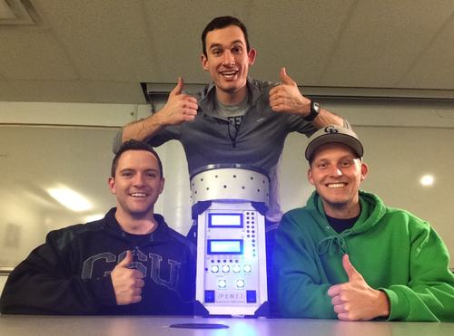
Matt Todd, Max Beard, and Kyle Roberts are three Mechanical Engineering students from Colorado State University who have designed a portable weather station.
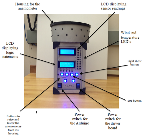
The Portable Electronic Weather Evaluator (PEWE) is equipped with multiple sensors: a barometric pressure sensor; an anemometer for measuring wind speed; an altitude sensor; and a thermistor to measure the change in temperature. On the PEWE's front panel, as seen in Figure 2, there are 10 LED's along the right side that light up proportionally to measure the wind speed as well as another 10 LED's that correspond proportionally to measure the temperature. There are also two LCD displays. The top LCD displays all of the sensors readings. The bottom LCD displays a logic statement corresponding to the sensors readings as well as the PEWE's introduction when the device is turned on. Below the LCD's are five LED's that, from left to right, display high temperature, low temperature, high altitude, high wind, and low pressure. These LEDs also correspond to logic statements that are displayed on the bottom LCD screen.

Under the 5 LED's, there is a row of four buttons. The two left most buttons control the raising and lowering of the anemometer. The two right most buttons control the SOS function and the light show. When the SOS button is pressed, the LEDs that surround the anemometer housing flash SOS in Morse code. Under these four buttons, there are two additional buttons that control the sound and the unit conversions. The user can switch between metric and SAE units as well as turn the buzzer on and off. PEWE has two power switches at the bottom of the front panel. The left most power switch is wired to a 9V battery which powers the Arduino. The right most power switch is also wired to a 9V battery that turns on the power to the driver board and supplies a 5V power source to the PIC16F88.

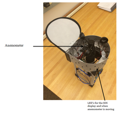
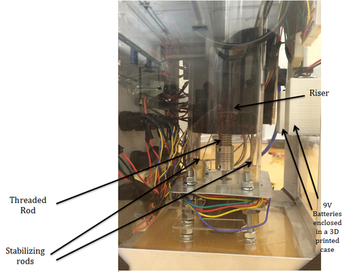
As seen in Figure 2, the housing for the anemometer sits on top of the PEWE. The anemometer sits on top of a 3-D printed riser which is attached to a lead screw by the use of a journal bearing. The lead screw and two stabilizing rods are used to convert the rotary motion of the NEMA 17 stepper motor to linear motion, as seen in Figure 4. This motion is used to raise and lower the anemometer. The stepper motor is controlled by a PIC microcontroller and an 'easy driver board.' The PIC tells the driver board which direction to turn the motor as well as sends pulses to the driver board which correspond to the amount of steps the stepper motor takes. The lead screw pitch has 12 threads per inch. The anemometer needed to be raised 3 inches therefore the stepper motor had to precisely controllable to make 36 rotations.


Download the full build instructions here.
Want to submit your own project to Gadget Freak? Email us! Be sure to include "Gadget Freak" in the subject line.
Allied Parts List | ||
Amt | Part Description | Allied Part # |
17 | LED;Blue;5mmDIA | |
18 | LED;Red;5mmDIA | |
13 | LED;Green;5mmDIA | |
3 | LED;Orange;5mmDIA | |
3 | LED;Yellow;5mmDIA | |
2 | LCD;20X4;Blue | |
2 | Switch;Rocker;ONOFF | |
2 | 9VoltBattery | |
4 | PushButton;Latching | |
2 | PushButton;Momentary | |
8 | 8/32 Screw | |
1 | ArduinoMEGA | |
8 | 8/32 Nut | |
8 | 330ohm;DIPResistor | |
1 | Capacitor;.2MicroFarrad | |
3 | Resistor;1K | |
1 | Resistor;10K | |
1 | StepperMotor;NEMA17 | |
1 | Wire;Hookup;Black | |
1 | Wire;Hookup;Red |
Other Parts List | |
Amt | Part Description |
1 | ShaftCoupler;5mm |
1 | ACMEThreadedRod;1/2in-12 |
2 | BrassRod;1/8in 2ft long |
1 | SheetMetal;Aluminum;4ftX4ft |
1 | AcrylicSheet;4ftX4ft |
1 | PLA;50mRoll |

About the Author(s)
You May Also Like


