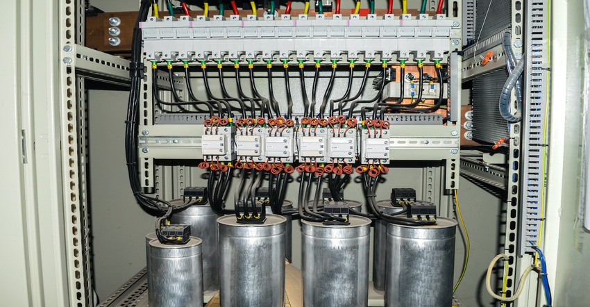
An impromptu video at DesignCon shows all and provides clues for testing electrolytic capacitors.
August 30, 2021

Ever wonder what goes on inside of an electrolytic capacitor? Nick Visic from AiSHi Capacitors shows how these popular capacitors work in this tear-down video from DesignCon. The screw terminal capacitors are large in size and characterized by high capacitance and voltage. They are used in industrial power supplies as well as new energy applications.
Now that we understand how electrolytic film capacitors are made, how are they tested?
Testing Capacitors
The simplest method to test a capacitor is by using a multimeter that has a capacitance setting. This method can measure capacitors ranging from few nano Farads to few hundreds of micro-Farads of capacitances.
If you have a low-end digital multimeter without a capacitance setting, then all you can do is test whether the capacitor is good or bad. A working capacitor will look like an open circuit when measured for resistance. A bad one will show some level of resistance after the transients have settled down.
Most engineers will remember testing a capacitor by measuring its time constant value. This test requires that the capacitance is known. The test will determine more precisely if the capacitor is good or bad. The trick is to measure the time constant of the capacitor to derive the capacitance from the measured time. If the measured capacitance and the actual capacitance are similar, then the capacitor is a good one. You’ll really want to use an oscilloscope for this test to accurately obtaining the time constant.
As a reminder, the time constant of a series RC (resistor/capacitor) circuit is a time interval required to charge the capacitor to 63% of the voltage of the source. In the RC time constant, also called tau, the time constant (in seconds) of an RC circuit is equal to the product of the circuit resistance (in ohms) and the circuit capacitance (in farads), i.e., tau =R x C. (Image Source: Inductiveload - Own work, Public Domain)

There are many other ways to test a capacitor. For beginners, though, it’s always best to properly discharge a capacitor before testing.
John Blyler is a Design News senior editor, covering the electronics and advanced manufacturing spaces. With a BS in Engineering Physics and an MS in Electrical Engineering, he has years of hardware-software-network systems experience as an editor and engineer within the advanced manufacturing, IoT and semiconductor industries. John has co-authored books related to system engineering and electronics for IEEE, Wiley, and Elsevier.
About the Author(s)
You May Also Like


