Don’t overlook the importance of the reliability of computer memory in automotive systems.
July 11, 2021

Aaron Boehm
A revolution in the auto industry is underway and the hardware that is driving it has an appetite for memory bandwidth. High-performance compute functions that run algorithms for perception, planning, and control in autonomous driving systems require faster, higher-capacity memory subsystems. In addition, the consumer’s digital world has been extended to the automobile.
In-vehicle infotainment systems are more immersive with features like speech recognition and 4K displays. The lines between infotainment and ADAS are increasingly blurred from a hardware perspective as these emerging functions share resources, making functional safety of these systems paramount.
But the role of memory in meeting system functional safety objectives is key and not well understood by much of the industry. It is important that those designing safety-critical systems understand the fail modes associated with the Dynamic random-access memory or DRAM, what DRAM offers with respect to diagnostic coverage, and how to achieve system safety objectives with the chosen memory technology.
It is necessary to have a high-level understanding of how components used in safety-critical systems are evaluated for compliance to the standard, ISO 26262 (Road Vehicles – Functional Safety). First, what is functional safety?
Functional safety is the avoidance of unnecessary risk of personal injury due to hazards caused by failure of E/E systems during the operation of the automobile. Fault risk analysis is defined by two categories, systematic and random hardware faults. While this article focuses primarily on random hardware faults, it is good to understand how systematic fault analysis plays a role in functional safety.
Systematic fault analysis is focused on the attempt towards fault avoidance. Examples of systematic faults are faults that occur during specification, design, manufacturing, etc. These types of faults could affect an entire fleet of automobiles. By adhering to a certified ISO 26262 process during the design and manufacturing of a device, an acceptable level of risk to systematic faults can be achieved.
Random hardware faults are inherent to semiconductor products and occur during the operation of the system. These are typically caused by some physical defect on a device but could occur as a result of other intervening factors. For DRAM, wear-out, thermal stress, package defects, and soft errors due to neutron flux are all examples of mechanisms that cause random hardware faults. To achieve acceptable levels of risk, automotive system designers need to put the focus on the detection of the random hardware fault.

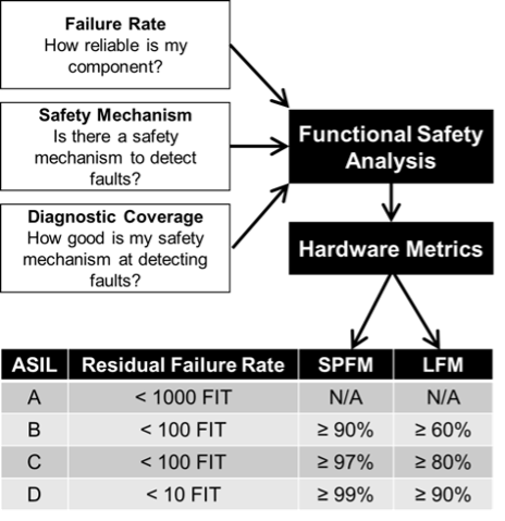
Figure 1 depicts how the key hardware metrics are computed through the functional safety analysis. Each Automotive Safety Integrity Level (ASIL) has a different set of requirements for the residual failure rate, Single Point Fault Metric (SPFM), and Latent Fault Metric (LFM). The SPFM is a hardware architectural metric that reveals whether or not the coverage by the safety mechanisms, to prevent risk from single point faults in the hardware architecture, is sufficient. Similarly, the LFM shows whether or not the coverage by the safety mechanisms, to prevent risk from latent faults, is sufficient.
The residual failure rate is the rate of the errors that are undetected and is expressed in Failures in Time (FIT), which equates to failures in 109 hours. The residual failure rate requirement is for the entire system and, typically, the DRAM subsystem would be budgeted 4% of the total. The resultant DRAM FIT budget would be 4 for ASIL B and 0.4 for ASIL D. As you can imagine, with the high-capacity memories that are being deployed in today’s systems, meeting these FIT requirements is challenging.
The foundation of the DRAM safety analysis is the Failure Modes, Effects, and Diagnostic Analysis (FMEDA). This is a bottom-up approach to breaking down all the DRAM functional blocks and determining possible fail mechanisms and the resulting fail modes. Using the information from the FMEDA, the system can determine the best ways to provide the diagnostic coverage required by ISO 26262.
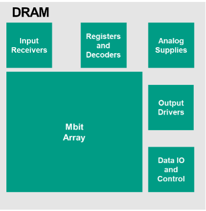
Traditionally, the focus of DRAM memory error detection and correction has been single-bit errors (SBE), in other words, SBE are corrected by the Error Correction Circuit (ECC). In reality, there are other ways that the DRAM can fail that require much more thought towards error detection and correction especially in a functional safety environment. Figure 2 shows a high-level block diagram of a modern DRAM.
You can see that there are many blocks of logic that make up the periphery of the device, not to mention the power distribution network. The diagram is not to scale, as in practice the Mbit array does make up most of the chip silicon area, but it is meant to show other blocks exist that must be considered in the safety analysis.

There are many fail modes on the DRAM, that can be mapped to a finite number of Top-Level Failure Modes (TLFM) as seen by the Host. As an example, there may be a fault in a row address decoder that produces a DRAM failure mode of “corrupted page of data”. This fail mode would map to TLFM-03 Corrupt data: Multi-bit error as shown in Table 1.

A brief description of the TLFM is helpful in understanding the system impacts and how to achieve the necessary diagnostic coverage. TLFM-01 through TLFM-03 are self-explanatory so I will focus on the remaining five. TLFM-04 is a repeated multiple-bit error (MBE) that occurs on every read cycle regardless of address. An example of this would be an open I/O (DQ) pin on the DRAM package. TLFM-05 is data read from the wrong address.
An example would be if the controller issues a read command to address A and through some fail mode on the DRAM data from address B is returned to the Host. These types of failure modes are very difficult to detect as the retrieved ECC code word will still be valid. TLFM-06 is lost or old data. This occurs when there is a failure on the write operation on a previous cycle to the same address. On the subsequent read of the address, it will retrieve “old” data that was never overwritten by the failed write.
Again, this is difficult to detect as the ECC codeword will be valid. TLFM-07 is a no-drive condition on a read. In the case of Low-Power Double Data Rate 4/5 or LPDDR4/5 DRAM, the DQ bus is terminated low and a no-drive condition will lead to all zeros captured by the Host. LPDDR is a type of double data rate synchronous dynamic random-access memory that consumes less power and is targeted for mobile computers.
This condition may or may not be an issue depending on whether the Host ECC implementation has the all-zero condition as a valid codeword. Lastly, TLFM-08 is a disturbance on the DQ bus that corrupts data during transmission across the physical link. This occurs in multi-rank systems where both ranks share the physical DQ bus and contention on the bus due to a fault on the memory causes corrupted data.
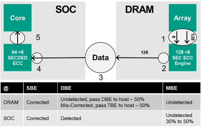
Let’s discuss the traditional approach to diagnostic coverage for the DRAM subsystem in automotive applications. Figure 3 shows a System on Chip (SoC) and DRAM subsystem (in this case LPDDR4). On a read cycle, at a byte level (8 DQ), 128 bits of data and 8 parity bits are fetched from the array (1) and run through the on-die SEC ECC engine.
SBE are detected and corrected and the 128b data packet is transmitted to the Host (2). Something of importance to note is that the corrections of DRAM array single bits are done at the internal I/O level. The cell that stores the bad bit is not overwritten as part of the correction process. This has implications with respect to dual point latent faults and affects the LFM metric shown in Figure 1.
The SoC in this example is running a 64 +8 single error correction, double error detection (SECDED) on the end-to-end data path. SECDED is an extended Hamming code that is popular in computer memory systems. These 8 parity bits are written and read like any other data by the DRAM. At the Host side, the data and parity bits are reconstructed into an ECC codeword and evaluated (4). 64 bits of corrected data are passed to the core (5). The table below the figure depicts the overall diagnostic coverage of this system. As you can see, this provides excellent coverage for single bit errors.
Data words with double-bit errors (DBE) are either passed to the Host uncorrected or, in roughly 50 percent of the cases, a miscorrect happens that turns the DBE into a triple bit error. This is inherent to the SEC ECC engine internal to the DRAM. The effect of this miscorrect is that the DBE from the DRAM get put into the MBE column at the Host, as it is now a triple bit error. Depending on the implementation of the Host SECDED, 30%-50% of the multiple bit errors will go undetected.

Now let’s go back to Table 1. Most of the FIT coming from the DRAM resides in TLFM-01 (single bit errors). Diagnostic coverage for these errors is relatively straightforward. But there is a significant percentage of the total critical FIT that resides in the multiple bit error bucket (TLFM-02 through TLFM-08). Some of these can be detected with common use SECDED schemes, while others will go undetected. With the traditional approach as shown in Figure 3, the amount of undetected FIT from DRAM multiple bit errors prohibits the system from reaching the key hardware metrics for each ASIL shown in Figure 1.
Where does this leave us? Obviously, there are gaps to closing the safety solution with traditional approaches. Luckily, Micron has been working on products that address these issues at both the DRAM and system levels. While the responsibility of assessing and meeting the system safety goals lies with the integrator, the memory supplier can help support the process.
As a system integrator focused on functional safety what should you ask your memory supplier? Make sure the systematic memory faults are covered through, ideally, an ISO 26262 certified process. Request the FMEDA analysis done on the product of interest. This analysis should include package and transient events. Ask about safety mechanisms deployed on the DRAM that address multiple bit errors, latent dual-point faults, and any other functionality that helps achieve the key hardware metrics as defined by the desired ASIL.
Aaron Boehm |
These are exciting times in the automotive industry. Advances in compute hardware are transforming the driving experience into something that resembles a scene from a science fiction movie. As cool as that is, functional safety must remain the priority for this movement to continue. That’s why industry players must remain focused on functional safety in memory and making safe technologies possible. Today I write this article in my office. Tomorrow? Maybe I am writing it in my car on my commute to work as the hardware does the driving.
Aaron Boehm has served in various architecture roles in Micron, with strong industry influence in the definition of DDR4, DDR5, and Wide IO2 DRAM technologies. Currently, Aaron is focused on memory innovation for meeting the high-performance and functional safety requirements in automotive. He has more than 132 issued or pending U.S. and international patents on areas ranging from DRAM architecture and circuits to memory security in automotive to V2X hardware sharing and smart roadway/city infrastructure. Prior to his focus on architecture, Aaron worked in product engineering at Micron.
You May Also Like


