Now’s the time to pull everything we’ve learned about LEDs together.
October 18, 2022
I find it difficult to believe we’ve reached the end of our NeoPixel odyssey. Arriving at our destination has taken me by surprise. I don’t have a speech prepared, and I haven’t got a thing to wear. I promised myself I wouldn’t cry. But here we are, poised to pull everything we’ve learned together.
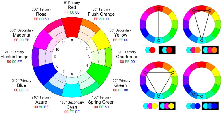
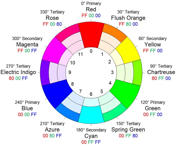
Let’s start by reminding ourselves of the color wheel we defined in Part 6 of this mega-mini-series. As I mentioned when we first introduced this diagram, I must admit that I’m rather proud of the little scamp because it boasts a host of useful information, including the 8-bit RGB values in hexadecimal. In particular, for the purposes of this column, observe the numerical annotations 0 through 11 (we will return to these in a moment).
I also mentioned that, when I’m playing with tricolor LEDs, one of the things I usually do early in my code is define all of these colors as follows (note that the line numbers have no meaning at this time beyond providing us with a point of reference).
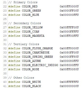
Remember that #define statements are used by the C/C++ pre-processor and they don’t consume any space in the microcontroller’s memory once the code is compiled. This means that you can add these definitions into all your LED/NeoPixel programs, even if you don’t plan on using all of the colors in any particular program.
Now, suppose we create an array called ColorWheel composed of our primary, secondary, and tertiary colors as follows:
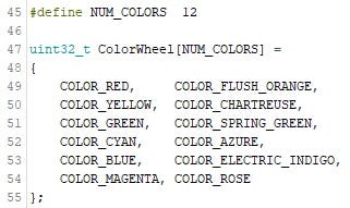
In this case, COLOR _RED will have an index value of 0, COLOR_FLUSH_ORANGE will have an index value of 1, COLOR_YELLOW will have an index value of 2, and so forth. Observe that the numerical annotations 0 through 11 on our color wheel image correspond to the index numbers of the elements in our ColorWheel array (it’s almost as if we had a plan).
Now, this is where things start to get interesting. Have you ever wondered why some color combinations are pleasing to the eye, while others set your nerves on edge? Well, the term “color theory” refers to practical guidance with respect to mixing colors and the visual effects associated with specific color combinations. Consider the following illustration, of which I’m also jolly proud, which reflects four common schemes: complementary, split-complementary, triadic, and analogous (there are a bunch of other schemes).
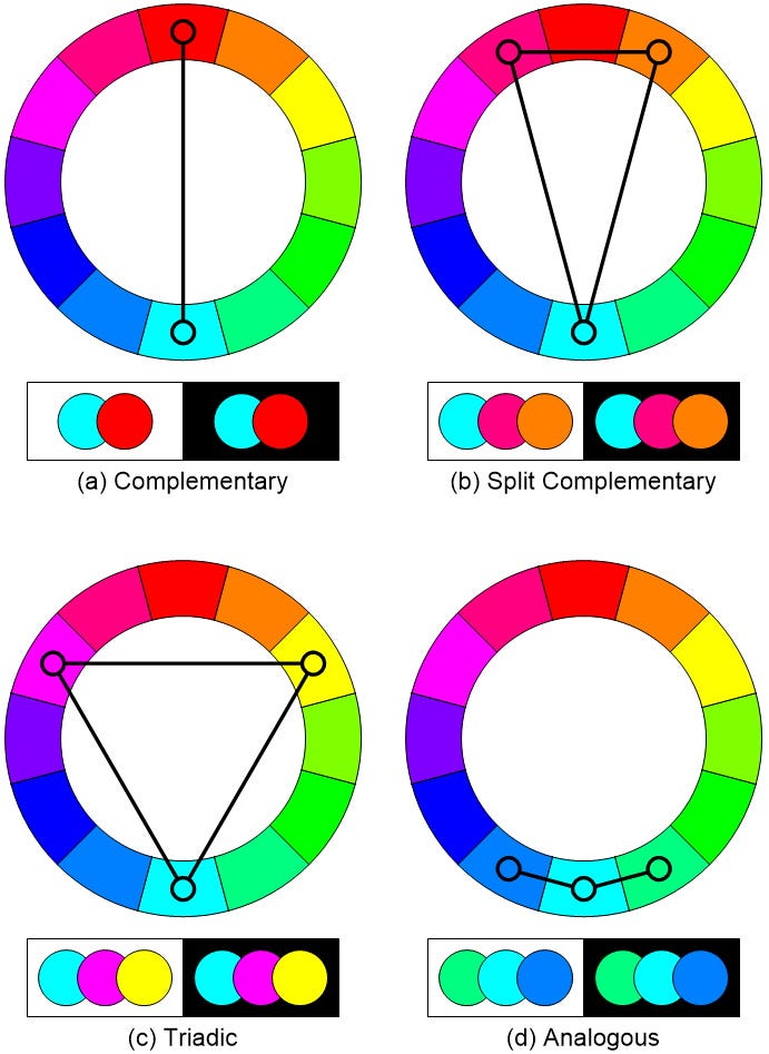
The term “complementary colors” refers to any two colors that are directly opposite each other on the color wheel, thereby providing maximum contrast. In the traditional red-yellow-blue (RYB) color model taught to kids, examples of complementary colors would be red-green, yellow-purple, and blue-orange.
As we discussed in Part 3, however, modern color theory uses either the cyan-magenta-yellow (CMY) subtractive color model for paints and pigments, or the red-green-blue (RGB) additive color model for light, in which case examples of complementary pairs are red-cyan, green-magenta, and blue-yellow.
On the bright side (no pun intended), the high contrast of complementary colors creates a lively look. On the other hand, these combinations can be a little jarring to the eye, so you might want to think twice before applying complementary colors to every room in your house.
The split-complementary (also called compound harmony) color scheme is a three-color combination consisting of base color and two colors that are 150 degrees and 210 degrees apart from the base color. Another way to think about this is that you start with a complementary color combination (two colors opposite each other on the color wheel), and then split one of them into its two adjacent colors on the wheel. As a result, the split-complementary color scheme has the same sharp visual contrast as the complementary color scheme but with less “pressure.”
The triadic color scheme is a three-color combination consisting of base color and two colors that are 120 degrees and 240 degrees apart from the base color. Triadic color schemes tend to be quite vibrant. Even when using pale or unsaturated versions of hues, this scheme offers a higher degree of contrast while also retaining the color harmony. According to Wikipedia, “This scheme is trendy among artists because it provides sharp visual contrast while maintaining balance and color richness.” The triadic scheme is not as contrasting as the complementary scheme, but it is easier to accomplish balance and harmony with these colors.
Analogous color schemes (also called dominance harmony) are groups of colors that are adjacent to each other on the color wheel, with one being the dominant color. The most pleasing effects are achieved when the dominant color is a primary or secondary color, while the two on either side are tertiary colors.
Suppose we declare an integer variable called iCol (“index pointing to a color”) to which we assign a color at random by using the Arduino’s random() function to generate a value between 0 and 11 (NUM_COLORS – 1) to index into our ColorWheel array.
Now suppose we want to determine the index value of its complementary color and assign this to an integer variable called iComp. Since we are currently working with 12 colors, we know that the complementary color will be 6 steps (halfway) clockwise around the color wheel. So, we could start by saying that iComp = (iCol + 6).
In reality, this is not the best way to go about things. In this case, the 6 would be known as a “magic number” because—to someone unfamiliar with this code—it seems to have appeared from nowhere. If we use NC as an abbreviation for NUM_COLORS, a better approach would be to use iComp = (iCol + (NC / 2)). This “future-proofs” our code against the day we decide to add more colors to our color wheel.
We haven’t finished yet, of course, because this works only half of the time. If the random number we generated was 0 (red), for example, then our complementary color will be 6 (cyan). If the random number we generated was 5, then our complementary color will be 11, which is still a valid number. But what happens if the random number we generate is between 6 and 11? In this case, our complementary numbers will be between 12 and 17, respectively, but our array contains only 12 values numbered 0 to 11, which means we have a problem.
This is where the modulo operator (‘%’) we introduced in Part 7 comes into play (this is one of my favorite operators). Remember that this operator returns the remainder from an integer division. So, what we need to do is modify our expression to be iComp = ((iCol + (NC / 2)) % NC) (I’m using a lot of parentheses in a desperate attempt to make things clear).
Let’s work through an example. Suppose we randomly generate an initial color of 9, which means our complementary value will be (9 + 6) % 12. Let’s work this through as follows: 9 + 6 = 15, and 15 % 12 = 3, which—if you look at our color wheel—is just what we wanted.
Using this complementary (a) algorithm as a starting point, we can use similar tricks to generate the split-complementary (b), triadic (c), and analogous (d) colors as follows:
(a) ((iNeo + (NC / 2)) % NC)
(b) ((iNeo + (NC / 2) – 1) % NC) and ((iNeo + (NC / 2) + 1) % NC)
(c) ((iNeo + (NC / 3)) % NC) and ((iNeo + ((NC / 3) * 2)) % NC)
(d) ((iNeo + NC + 1) % NC) and ((iNeo + NC – 1) % NC)
In reality, we’ve only scratched the surface of this interesting topic. There are so many other things I want to talk about, but I think we’ve covered enough ground for the moment. The main thing is that I would like to hear from you. Has this mega-mini-series proved useful? Which parts did you like the most? Do you still have unanswered questions? As always, I welcome your comments, questions, and suggestions.
About the Author(s)
You May Also Like


