Hundreds of NeoPixels can be controlled using a single microcontroller pin.
July 27, 2022

Hi there, and welcome to Part 4 of this ever-growing mega-mini-series. In Part 1, we discussed the first vacuum tube diodes, moved on to their solid-state (semiconductor) descendants, and then progressed to their light-emitting cousins. In Part 2, we introduced the concepts of forward voltage drop (VF) and maximum forward current (IF), current-limiting resistors, and different ways to control discrete (individually packaged) LEDs using switches and microcontrollers (MCUs). Most recently, in Part 3, we introduced the concepts of pulse-width modulation (PWM), additive and subtractive primary colors, and tricolor red, green, and blue (RGB) LEDs.
Now, finally, we are going to sink our metaphorical teeth into tricolor LEDs suitable for the 21st century in the form of WS2812 devices, which popularly go by Adafruit’s NeoPixel moniker. But... before we proceed... since we are talking about light and colors and suchlike, I was just wondering if you were aware of a rather amazing experiment that completely blew (what I laughingly call) my mind.
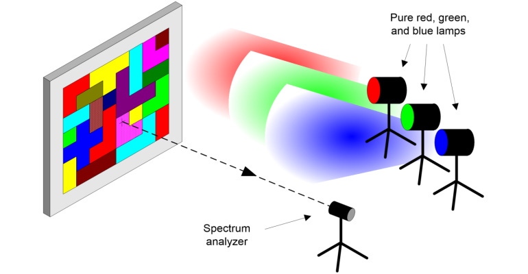
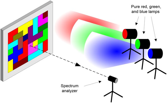
As we know from work performed by English mathematician and physicist Sir Isaac Newton using a glass prism circa 1665, white light (in the form of daylight) can be split into all the colors of the rainbow. Newton also passed all of these colors through a “reverse prism” causing them to recombine into white light. I tell you; that must have been a “Tra-La!” moment if ever there was one. Bearing this in mind, consider the image below:

We start with pure RGB spot lamps combining to form white light that’s used to illuminate a board. When I saw this experiment performed, the board was about 10 feet square and covered with a conglomeration of geometric shapes presented in a kaleidoscope of colors.
Now observe the spectrum analyzer, which can be used to determine the quantities of RGB light being reflected from any of the geometric shapes.
The experiment commences by recording the RGB reflected from one of the shapes—let’s say a pinkish-brown. The spectrum analyzer is then pointed at a different shape with a completely different color—let’s say a greenish-yellow. Not surprisingly, this second color has a completely different RGB profile.
Now, sit up and pay attention because this is the clever part. Leaving the spectrum analyzer pointing at the greenish-yellow shape, the intensities of the RGB light sources are varied until the RGB profile being reflected matches that of the pinkish-brown shape.
So, what color do you think the greenish-yellow shape looks now? Intuitively, you might guess “pinkish-brown,” but you’d be wrong because all of the colors continue to look the same as they did before! What? How? Why?
Next, a 10x10-ft square of white card is placed in front of the board. This card has a hole with the same footprint as the greenish-yellow shape, which immediately changes to look pinkish-brown!
The explanation for this magic is that if we can see only the one shape, then our brains have no other recourse than to “assign” it a color based on the RGB values being reflected from that shape. However, if the shape is seen in the context of all the other colors, our brains perform some incredibly clever signal processing to decide what colors the shapes should have, and these are the colors that are presented to the conscious portions of our minds. All I can say is “Wow!”
But we digress ... The image below shows a single WS2812, whose actual size is only 5 x 5 mm square and about 1 mm thick. In addition to RGB sub-LEDs (the three small squares in the lower half of the circle), there’s also a teeny-tiny controller (the larger black rectangle in the upper half of the circle). This controller contains three 8-bit PWM functions—one for each of the sub-LEDs—and a communications function that allows it to receive data from a microcontroller (or an upstream WS2812) and transmit data to a downstream WS2812.
![]()
NeoPixels may be presented in a variety of ways, from individual packages as shown above, to rings, to bars, to arrays, to long strips. If you plan on using them as individual devices, then each WS2812 should be accompanied by a 0.1-uF capacitor between its power and ground pins (when multiple devices are presented as rings or strips, these capacitors will already be included). Speaking of power, WS2812 devices will operate anywhere from 4 V to 7 V, while their WS2812B cousins will operate anywhere from 3.3 V to 5 V. I personally always run mine at 5 V because (a) it makes my life simple and (b) they are as bright as bright can be at 5 V.
These clever little scamps have four pins: power (5 V), ground (0 V), Data-In, and Data-Out, thereby allowing them to be daisy-chained together as illustrated below. As a result, hundreds of the little rascals can be controlled using a single output from a microcontroller (contrast this to standard tricolor LEDs, each of which requires three of the microcontroller’s pins).
![]()
Observe the 390-Ω resistor (any value between 300 Ω to 500 Ω will do). This is used to dampen overshoot and undershoot caused by the microcontroller’s fast output transitions. This resistor should be mounted as close to the first pixel’s Data-In terminal as possible (note that many products like Adafruit’s NeoPixel rings already include this resistor).
One problem I occasionally run into is if I wish to use a microcontroller with 3.3 V outputs, such as the Seeedunio XIAO. This little beauty is only the size of a regular postage stamp, but it packs a punch with a 32-bit Arm Cortex-M0+ processor running at 48 MHz with 256 KB of flash memory and 32 KB of SRAM.

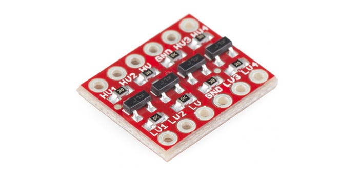
As we previously discussed, I prefer to run my NeoPixels at 5 V, which means I need to perform some form of voltage level shift. One option would be to use some form of 3.3 V to 5 V voltage level converter breakout board (BOB) to drive the NeoPixel string. For example, the folks at SparkFun make a very tasty 4-bit bi-directional level shifting BOB. However, using this when we need only a single unidirectional bit would be somewhat wasteful. If only we knew a cunning trick...
Well, the WS2818 data sheet says that a logic 1 = 0.7 x Vcc or higher. If we assume Vcc = 5 V, then 0.7 x 5 V = 3.5 V. Since data sheets tend to be conservative, the 3.3 V signal from the XIAO may still work but this is not guaranteed. The cunning trick solution is to sacrifice the first pixel in the chain by powering it via a IN4001 diode as illustrated below.
![]()
The IN4001 diode has a 0.7 V forward voltage drop, which means that the first pixel is now being powered by its modified Vcc of 5 V – 0.7 V = 4.3 V. Remembering that the WS2812 sees a logic 1 as being 0.7 x Vcc or higher, we’re now talking about 0.7 x 4.3 V = 3.01 V, so the 3.3 V signal from XIAO is good to drive the first pixel. Furthermore, the 4.3 V output from the first pixel is good to drive the second pixel, which is looking for anything higher than 3.5 V. I don’t know about you, but I feel another “Tra-La!” is in order.
As one final thought, we can still use the “sacrificial” pixel for some purpose if we wish, so long as we remember that it will be dimmer than the other pixels (assuming we are running them all at the same brightness, of course).
Well, that’s all for now. In my next column we will start to create programs to drive these little scamps. Until then, as always, I look forward to seeing your comments, questions, and suggestions.
About the Author(s)
You May Also Like


