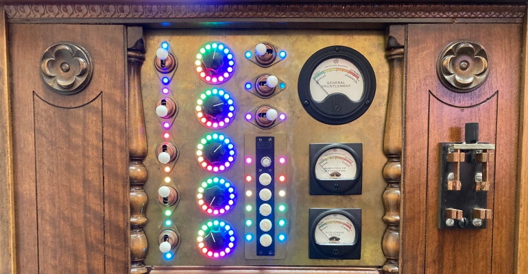
I have a simple rule of thumb that there is no such thing as having too many LEDs.
June 20, 2022

I spend quite a lot of time giving talks to newcomers to the world of electronics. There are some topics that never seem to grow old. One of these is the subject of light-emitting diodes (LEDs). Even in the case of professional engineers, many of them have focused on certain application areas—like developing software—to the extent that they’ve forgotten much of what they learned on the LED front in their college days. On this basis, I’m going to start at the very beginning with standard diodes, then unicolor LEDs, then regular tricolor LEDs, and finally WS2812 tricolor LEDs. The latter are popularly known as NeoPixels, which is Adafruit’s name for these little beauties.
Before we start, there’s one issue we should dispense with from the get-go, which is should we say, “a LED “or “an LED”? Anyone who favors one form invariably finds that the other “grates on their nerves.” In fact, both are correct. It all depends on whether you say/think the word LED by spelling it out as “L-E-D,” in which case “an LED” is the appropriate usage, or if you say/think it as “LED” to rhyme with “bed,” in which case “a LED” is the way to go. In my case, I may use either form depending on my mood of the moment (that’s how good I am).
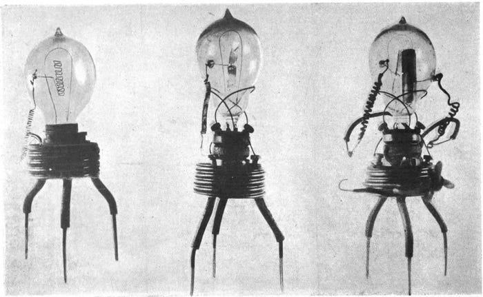
One of the key things about diodes is that they conduct electricity in only one direction, which is a pretty good trick when you come to think about it. The first type of diode was implemented as a vacuum tube in 1904 by the English electrical engineer and physicist John Ambrose Fleming. This tube was of a type classed as “thermionic” because it utilized the thermionic emission of electrons (i.e., the liberation of electrons from an electrode by virtue of its temperature) from a hot cathode. These electrons travelled from the negative cathode to a positive anode (as we will see, knowing this nugget of knowledge helps explain the naming conventions for solid-state diodes).

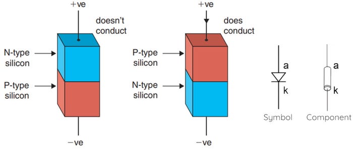
These days, of course, most of us work with solid-state diodes created out of semiconducting materials. For example, a pure silicon crystal can be “doped” by adding other elements into the crystal lattice, such as phosphorous to create N-type silicon and boron to create P-type silicon (all of this is discussed in excruciating detail in my book, Bebop to the Boolean Boogie: An Unconventional Guide to Electronics).

If the N- and P-type ends are connected to +ve (positive) and -ve (negative) potentials, respectively (as shown above on the left), then the diode will not conduct. Contrariwise, if the N- and P-type ends are connected to -ve and +ve potentials, respectively (as shown above on the right), then the diode will conduct.
Observe that the arrow indicating current in the right-hand diagram is shown in the classical sense indicating a flow of electrons from positive to negative. In the real world, electrons are transported from a more negative potential to a more positive potential.
At first glance, this may appear to be a rather fundamental thing to get wrong. The problem is that humans discovered electricity (or electricity, in the form of lightning, discovered humans) some time before we knew about things like atoms and protons and electrons. For a variety of reasons–some theological in nature–it was collectively assumed and agreed that electricity “flowed” from a positive source to a negative destination. By the time we discovered things like electrons, all of the textbooks had the arrows for current pointing the wrong way. Ultimately, we decided to leave the textbooks “as is” (or “as was,” as the case might be), on the basis that engineers knew what was really happening and the masses would never know the difference anyway.
In general terms, a polarized component can be connected into a circuit in only one direction; the “anode” is the electrode through which the conventional current enters into a polarized component, while the cathode is the electrode from which the conventional current leaves a polarized electrical device. A diode is a polarized device. When the anode (a) end of the diode is connected to a more positive potential and the cathode (k) end is connected to a more negative potential, the diode will conduct. The triangular symbol points in the direction of classical current. In the case of a discrete lead through-hole (LTH) packaged component, there will be a ring on the cathode end.
Why ‘k’ (or ‘K’) for cathode rather than ‘c’ (or ‘C’)? I’ve heard several explanations. One is that the designers of early computer-aided design (CAD) tools used C, E, and B to represent the collector, emitter, and base terminals on bipolar junction transistors (BJTs); they used S, D, and G to represent the source, drain, and gate terminals on field-effect transistors (FETs); thus, they decided to use K to avoid confusion with the C for collector. I don’t know about you, but I’m prepared to accept this unless someone provides a more compelling explanation.
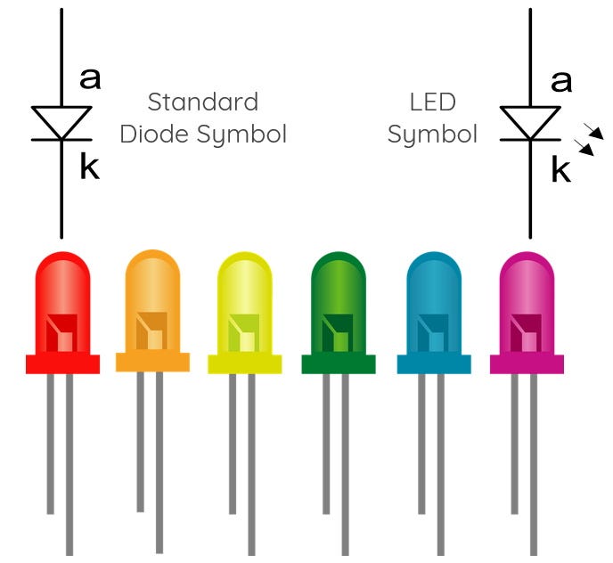
Like a regular diode, a LED conducts electricity in only one direction. Unlike a regular diode, when electricity is flowing through a LED, it will emit light from its P-N junction. Thus, the symbol for a LED includes two or three little arrows which indicate the light being emitted.

The first visible light LEDs, which appeared on the scene in 1961, were incredibly expensive (we’re talking around $200 apiece, and this was in the days when even $1 was nothing to be sniffed at). By the beginning of the 1970s, however, they could be obtained for around five cents each, at which point they found a wide variety of uses in consumer applications (e.g., calculators and wristwatches) and industrial applications (e.g., test equipment and instrumentation panels).
At first, you could have any color you wanted so long as that color was red. Eventually, other colors made their debuts, including yellow, orange, green, and blue. These days, LEDs are extremely affordable. I just did a quick Google while no one was looking to find a box of 1,000 LEDs in five different colors (blue, yellow, red, green, and white) for only $9.99 on Amazon.
In Part 2 of this mega-mini-series, we will cogitate and ruminate on different ways to control unicolor LEDs before taking the bold step to address their tricolor cousins. In the meantime, as always, I welcome your comments, questions, and suggestions.
About the Author(s)
You May Also Like


