Opening new horizons in automotive LIN master solutions with a new step in ECU integration and design.
January 28, 2022
Rainer Evers
Local Interconnect Network (LIN) automotive bus systems are mainly placed in the body domain and we experience a constantly increasing number of nodes in the car. This article introduces the concept of a Serial Peripheral Interface (SPI)-to-Multiple-LIN bridge that will significantly change the way how LIN automotive bus systems will be connected to the microcontroller of the electronic control units (ECU) in the car.
The SPI-to-LIN-bridge concept allows the host microcontroller unit (MCU) to be fully tailored to the application performance requirements. Besides significantly reducing the bill of materials (BOM) and board space consumption, this concept also greatly enhances the flexibility and scalability of multi LIN master channel architectures.
We conclude with an example of a multi-channel LIN master application with SPI-to-LIN bridge, based on NXP’s SJA1124. The SJA1124 is a LIN transceiver incorporating four LIN master channels, each with an integrated master controller and master termination. By integrating the master termination along with the master controller, bill-of-material (BOM) and board space are clearly reduced.
Introduction
More and more applications have multiple LIN master channels. Moreover, the number of LIN channels per application is also increasing, whereas the available space for these applications is typically shrinking.
In this paper, SPI-to-LIN bridge-based solutions for multi-channel LIN applications are described. It explains how board space and BOM are reduced and how the scalability and flexibility of the application architecture and MCU variety are enhanced.
MCU limitations
On-chip LIN features
There is a wide range of integrated MCU features supporting LIN applications, varying from a simple UART to a full-featured LIN controller. The number of integrated LIN channels also ranges from a few to many, but typically depends on the MCU performance platform.
Pin count
For each LIN channel, at least two pins are required, which are the pins TXD and RXD. In addition, one or more mode control pins might be necessary to switch the LIN transceiver mode from low power mode to normal mode and vice versa.
Thus, for applications with multiple LIN master channels, the number of necessary pins accumulates with at least a factor of two. For instance, for 8 LIN channels 16+ pins are required. The example in Figure 1 illustrates the necessary MCU pin count for two quad LIN transceivers, connected in the traditional way with pairs of TXD and RXD per LIN Channel.
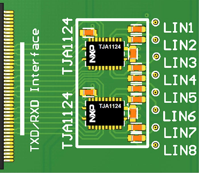
If the MCU pin count is already critical, the high number of pins required for multiple LIN master channels might force the selection of the next higher and more expensive MCU family variant with more pins, if available – what is not always the case. This leads to a significant increase in the BOM and, herewith, costs.
Number of on-chip UART/LIN controllers
As part of the on-chip peripherals, the available number of integrated UART/LIN controllers depends typically on the performance class of the MCU family, i.e. the higher the performance class, the more LIN channels are integrated. The choice of a high-end/high pin count MCU (bigger footprint) might be necessary, although the higher MCU performance is not needed from an application perspective.
Furthermore, the higher the required number of integrated UART/LIN controllers, the smaller the range of available MCU families. Worst case, no MCU variant with sufficient UART/LIN controllers is available within the preferred MCU family. Potentially, even a changeover to a new MCU architecture might be unavoidable. This basically means that the number of LIN channels is driving the MCU choice, instead of the required performance.
Flexibility and scalability through SPI interface
What if the LIN controller would move into the LIN transceiver? With the integration of a LIN controller into a LIN transceiver device, the TXD and RXD signals between MCU and LIN transceiver are eliminated. Instead, a standard MCU interface for peripherals can be used, such as the Serial Peripheral Interface (SPI).
Such a LIN device, with on one side an SPI and on the other side a LIN bus interface, is called an ‘SPI-to-LIN bridge’.
MCU selection decoupled from LIN channel count
Moving the LIN controller from the MCU into the LIN transceiver decouples the MCU selection from the number of LIN channels. The number of UART/LIN controllers integrated into the MCU is not a relevant/limiting factor anymore. In fact, no integrated UART/LIN controller is needed at all. To accomplish LIN communication, the MCU just needs to feature a standard SPI function.
As an SPI-to-LIN bridge decouples the MCU selection from the LIN channel count, the required MCU performance becomes the primary selection criterion, rather than the number of LIN communication channels that need to be handled. Thus, this widens significantly the range of suitable and available MCUs.
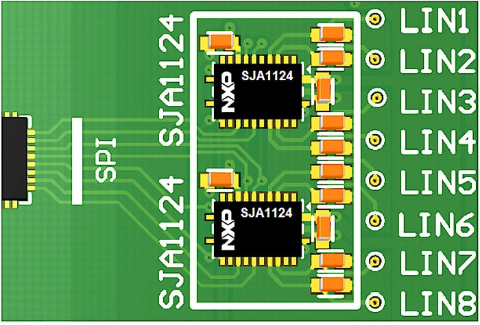
8 MCU pins for 8 LIN master channels based on SPI-to-QuadLIN bridge
With SPI, the required number of MCU interface pins becomes almost independent from the number of LIN channels. This pays off the most for higher numbers of LIN channels. For instance, an SPI-to-LIN bridge with four integrated LIN channels would require 1 additional MCU chip select pin for scaling up from four to eight LIN master channels. Figure 2 illustrates an MCU pin count example with two SPI-to-QuadLIN bridges.
Depending on the computational footprint of the application, this opens up the use of smaller, mainstream low-pin-count MCUs.
Furthermore, an SPI-to-LIN bridge enables upgrading of legacy applications with additional LIN channels, despite the applied MCU does not provide the extra required UART/LIN controllers.
Hardware independent LIN software driver
Due to the LIN controller moving out of the MCU, the AUTOSAR LIN Driver becomes independent from the MCU hardware. Like the AUTOSAR LIN Transceiver Driver, the LIN Driver depends now on the SPI-to-LIN bridge implementation only, using the standard SPI hardware of an MCU. For this reason, the LIN Driver of an SPI-to-LIN bridge becomes part of the AUTOSAR Communication Hardware Abstraction.
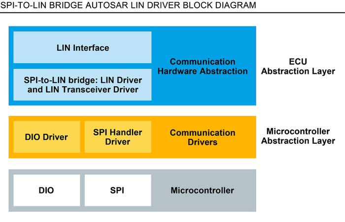
As illustrated in Figure 3, both, LIN Transceiver Driver and LIN Driver are located between AUTOSAR LIN Interface and SPI Handler / Driver. As such, it can be either part of the AUTOSAR ECU Abstraction Layer software from a software vendor or an add-on to AUTOSAR Microcontroller Abstraction Layer (MCAL) packages from a microcontroller vendor. This enables fast reuse of the LIN software driver for different MCU implementations.
SPI performance is key
The use of an SPI as an MCU interface for multiple LIN channels consequently sets the focus on the SPI performance, because it becomes the bottleneck for the LIN data flow. The SPI runtime is the limiting factor for the data throughput. Therefore, it is also limiting the maximum number of LIN channels, which can be adequately served by one SPI.
The SPI runtime depends on the chosen hardware (MCU and SPI-to-LIN bridge) and software implementation (SPI Handler / Driver). Due to the diversity of MCU SPI implementations (optimized for die size or low power or speed, etc.) and SPI software driver implementations (optimized for code size or speed, etc.), a generic maximum number of operable LIN channels per SPI is hard to give. Typically, one SPI should be able to serve at least 8 LIN channels.
Board space more and more under pressure
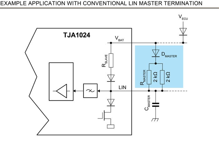
A conventional LIN master termination is built-up with discrete parts, such as 1 or 2 pull-up resistors and 1 diode. This means that max. 3 discrete parts per LIN master channel are needed, as highlighted in Figure 4.
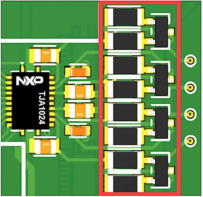
In applications with several LIN master channels (e.g. 4 LIN channels), the board space consumed by the LIN master termination may become a constraining factor, especially when the total available board area is already tight. The red frame in Figure 5, shows the LIN master termination board space for 4 LIN master channels.
Applications with multiple LIN channels are typically LIN master applications. For this reason, the integration of the LIN master termination into the LIN transceiver is a logical step for multiple LIN channel transceivers.
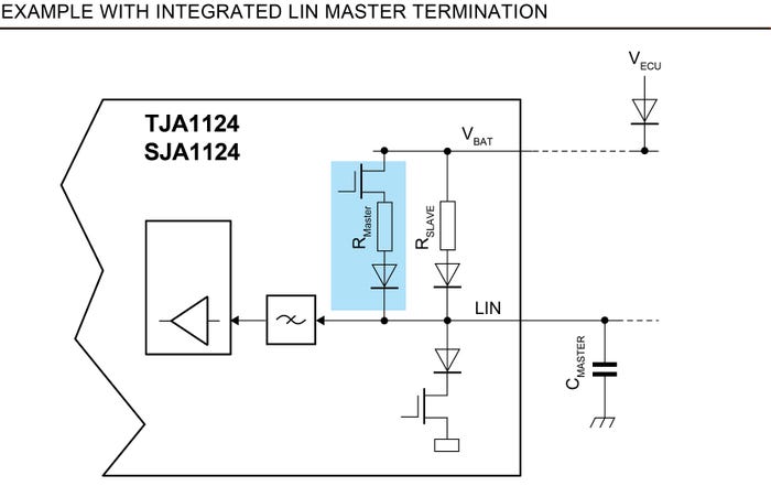
A high-side switch is added to the integrated LIN master termination circuit to cut off the short-circuit current through the LIN master pull-up resistor for fault cases such as a LIN short-circuit to ground. Figure 6 shows an example in which the integrated LIN master termination is highlighted.
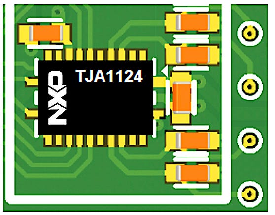
With having integrated the LIN master termination, the LIN-related board space for applications with several LIN master channels (e.g. 4 LIN channels) depends mainly on the number of LIN channels per LIN transceiver and the device package outline. Here, a leadless package with an exposed pad combines small size with a good thermal connection to the board. Figure 7 shows the board space consumed by a quad LIN transceiver with integrated LIN master termination.
Application example: SPI-to-Quad-LIN bridge based on NXP’s SJA1124
An SPI-to-LIN bridge device is available from NXP. The SJA1124 [1] is an SPI-to-Quad-LIN bridge device incorporating 4 LIN channels. Each LIN master channel contains a LIN controller and LIN transceiver with master termination. LIN data communication is accomplished via SPI. The SJA1124 converts the transmit data stream received on the SPI input into LIN master frames on the LIN bus. The data stream received on the LIN bus can be read via SPI. A complete LIN frame can be transmitted in one single SPI operation.
As shown in the example in Figure 8, 8 LIN channels can be built up with two SJA1124 devices. In this configuration, 5 MCU pins are needed for the SPI communication (clock, data in, data out, chip select 1, and chip select 2). The on-chip baud rate generator in the LIN controllers requires a reference clock signal. For detection of interrupt events, one shared external interrupt MCU input or two dedicated external interrupt MCU inputs can be optionally connected to the interrupt output of the SJA1124, respectively.
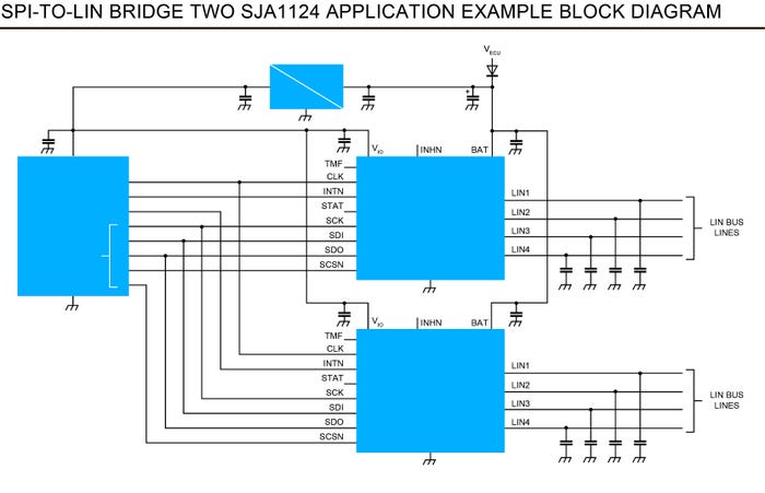
Figure 8: SPI-to-LIN bridge application example with 8 LIN channels built up of two SJA1124 from NXP
Due to the SPI data transfer and the integrated LIN master termination of the SJA1124, the BOM and board space can be significantly downsized. Moreover, the range of suitable MCUs is considerably wider.
Summary/Conclusion
With the introduction of an SPI-to-LIN bridge with integrated LIN master termination, the BOM, board space, and costs for multi-channel LIN applications are significantly reduced:
Less discrete components
Less MCU interface signals
Decoupling the MCU from the LIN interface, by moving the LIN controller out of the MCU, offers unprecedented flexibility:
Ability to tailor the MCU choice to primary application criteria
Enhances scalability through MCU independency from LIN channel count
Fast reuse of the SPI-to-LIN bridge software driver for different MCU implementations
Simplifies redesign of legacy designs, if (more) LIN connectivity is required
|
Thus, an SPI-to-LIN bridge like NXP’s SJA1124 is the perfect companion device for MCUs to handle a high number of LIN master channels, offering unprecedented cost and board space savings in multi-channel LIN applications.
Rainer Evers, Principal System Engineer, NXP Semiconductors, is a system engineer with more than 20 years of experience in the semiconductor industry. Throughout his professional career, at NXP Semiconductors and prior at Philips Semiconductors, he focused on automotive CAN, LIN, and Ethernet transceivers. In his role, he is responsible for transceiver product definition and represents NXP as an expert in LIN standardization in ISO and SAE.
You May Also Like


