Sign up for the Design News Daily newsletter.
Traditional dev kits are based on a manufacturer’s microcontroller, radio module, or sensor device. The idea is to aid the design engineer in developing his or her own IoT prototype as quickly as possible. A not-so-traditional IoT development kit released by Bosch aims to simplify IoT prototyping even further.
February 9, 2016
5 Min Read
.svg?width=850&auto=webp&quality=95&format=jpg&disable=upscale "Bosch XDK Development Kit Puts an End to Component Mix-and-Match")
Traditional development kits are based on a manufacturer’s microcontroller, radio module, or sensor device. The idea is to aid the design engineer in developing his or her own IoT prototype as quickly as possible. A not-so-traditional IoT development kit released by Bosch aims to simplify IoT prototyping even further.
A typical IoT design includes a sensor subsystem, an RF subsystem, and a host microcontroller complex. It is up to the design engineer to mix-and-match components within the subsystems to meet the device’s design criteria. Once the initial prototype is realized, the design engineer is often forced to change hats and begin the firmware generation phase of the design. With the introduction of the XDK110 Cross-Domain Development Kit, the Bosch Connected Devices and Solutions team has eliminated the component mix-and-match process to reduce the time required to implement an IoT firmware solution on a prototype platform.
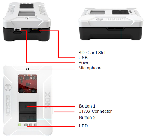
Bosch's XDK110 Cross-Domain Development Kit is a self-contained device with an ARM Cortex M3 MCU at its heart.
(Source: Bosch Connected Devices and Solutions)
The XDK110 is a self-contained IoT development device that incorporates eight MEMS sensors, a Bluetooth Low Energy radio, and a low-power 802.11b/g/n WiFi radio. Access slots in the XDK110’s enclosure expose a microSD card socket, a downstream USB port, an expansion gateway interface, and a 10-pin J-Link header. A trio of user-accessible LEDs and a pair of programmable pushbuttons fill out the XDK110 package.
All of the hardware is under the control of a Silicon Labs ARM Cortex M3 EFM32GG390F1024 microcontroller. Power is provided by an internal 560mAh Li-Ion rechargeable battery. The internal battery is automatically charged via voltage applied to the XDK110’s USB portal.
[Learn more electronics trends and developments THIS WEEK at Pacific Design & Manufacturing, Feb. 9-11, at the Anaheim Convention Center.]
Firmware support for the XDK110 is provided by the XDK Workbench, which is obtained as a free download from the Bosch website. The XDK Workbench is based on the Eclipse IDE and includes all of the drivers, compilation components, and API code necessary to write, compile, and run or debug an XDK110 application. The XDK Workbench relies on the open-source services of FreeRTOS, EMLIB, and the GNU-ARM-GCC tool chain.
Program examples, demos, API source code, and a toolbox are also included in the XDK Workbench download package. XDK Workbench interfaces to the XDK110 hardware via the XDK110’s integral USB port. Flashing and bootloading can be accomplished through the USB connection. Debugging requires a J-Link debug probe, such as the J-Link PRO to be attached to the XDK110’s JTAG interface. You will need to obtain a J-Link 9-pin Cortex-M Adapter to use a J-Link Debug Probe with the XDK110. XDK Workbench automatically determines if a J-Link device is attached. XDK Workbench also automatically detects the presence of a USB-attached XDK110.
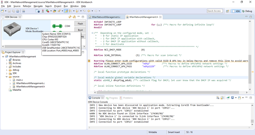
XDK Workbench is based on the Eclipse integrated development environment.
(Source: Bosch Connected Devices and Solutions)
XDK Workbench is intuitive and easy to use. I was able to get the Accelerometer Data Over BLE example application up and running in a matter of minutes. Debugging the example application was as easy as plugging in my J-Link PRO and clicking on the XDK Workbench debug button.
READ MORE ARTICLES BY FRED EADY ON DESIGN NEWS:
The engineer in you will want to take a peek under the XDK110’s hood, but there’s no need for that. All you have to do is study the XDK110 libraries to get an idea of what is mounted on the XDK110 printed circuit board. The microSD card is driven by FATFs, which happen to be a popular open-source file system. The WLAN driver is based on TI CC31xx/CC32xx code. The XDK110’s sensor array consists of Bosch and Maxim Integrated components that are listed in the XDK110 User Guide.
The XDK110’s ARM Cortex M3 EFM32GG390F1024 microcontroller hails from the Silicon Labs Giant Gecko family. Just in case you need access to additional EFM32GG390F1024 GPIO pins, the XDK110 package comes with an XDK Gateway pod. The XDK Gateway pod attaches to the XDK110’s gateway interface via a ribbon cable that is part of the XDK110 hardware package.
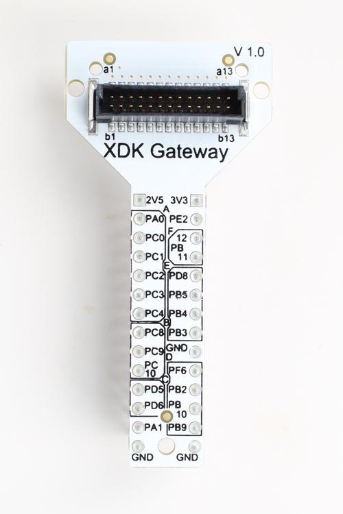
XDK Gateway pod.
(Source: Bosch Connected Devices and Solutions)
The XDK110 Cross-Domain Development Kit is a beautiful piece of engineering. The hardware design is solid, and XDK Workbench is a well-thought-out firmware support solution. If your engineering demon gets the best of you, the XDK110 enclosure is secured with a pair of 0.050-inch hex head screws.
Fred Eady is the owner of EDTP Electronics, which was established in 1988 following the publication of his first magazine article. Since the formation of EDTP Electronics, Fred has written thousands of magazine articles. He has written for all of the major electronic magazines, including Radio Electronics, Electronics Now, Nuts and Volts, Servo, MicroComputer Journal, and Circuit Cellar. To date, he has authored four books and contributed to a fifth. He currently works as a PIC microcontroller consultant and is a Microchip Authorized Design Partner. Fred also authors monthly columns in Nuts and Volts and Servo magazines. His customers include machine shops, specialty startup companies, medical machine manufacturers, coin-operated device businesses, and various other research and development companies. He has a very close working relationship with Microchip Technology, the manufacturer of PIC microcontrollers, and has taught Ethernet and WiFi classes at Microchip's annual Masters Conference.

You May Also Like
Editors' Choice


Jun 4 - Jun 6, 2024
Jun 4 - Jun 6, 2024
Innovation in automation starts here. Discover and collaborate on automation solutions that are revolutionizing the entire production lifecycle — from design to production to market — and sharpen your competitive edge. ATX South is part of IME South, a six-in-one expo offering the latest insights & solutions spanning medtech, packaging, automation, plastics, design, & processing.
Register Now