Just as people have senses that transmit movement and position to their brains, autonomous vehicles employ a collection of electronic sensors to keep them true to their intended pathways.
September 13, 2021
James Fennelly
Everybody knows about GPS, which is an acronym for the Global Positioning System, America’s satellite navigation system. Together with its foreign counterparts, including GLONASS, Galileo, and Beidou among others, they are known collectively as the Global Navigation Satellite System, or GNSS. What more does an autonomous or a semi-autonomous vehicle need? Plenty, as we will see.
GPS can pin down a location to within a few meters. That’s great to tell you where you are, and to help point the way to your next appointment. Everybody uses these systems every day, and they’re great – how did we ever live without them?
But You Can’t Place All Your Bets with Satellite Positioning
But pinning down a location to within a few meters can’t tell you if you’re drifting into the next lane. Nor will it tell you if you are dangerously close to another vehicle. There is another technology, real-time kinematic positioning (RTK), which enhances GNSS / GPS to pin down locations to within a few centimeters or so.
Access to GNSS / GPS or RTK satellite data is generally obtained through GNSS / RTK receivers integrated with a RTK positioning engine. Additionally, they are often further integrated with an inertial measurement unit (IMU), and inertial navigation algorithm, such as ACEINNA RTK330LA and OpenRTK330LI. These devices serve vital absolute localization functions, as we’ll soon see.
And with units like ACEINNA’s RTK330LA, the cost of Inertial Navigation Systems (INS) is coming down to a level suitable for ordinary passenger vehicles.
RTK calls for a group of GPS/GNSS satellites communicate with both the base station and the vehicle being tracked. The latter two are in contact with each other via the cellular system. Because the base stations know their precise location, this puts into place a mechanism for error correction, and the vehicle’s location can now be determined to within a few centimeters, as described.
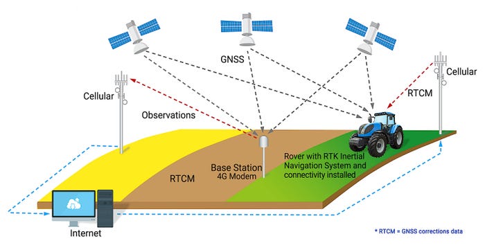
However, RTK depends on separate “base station” receiver/transmitter systems within about 30 miles of the vehicle. It’s the nexus of the satellite, the vehicle’s reception, and the base station’s reception, along with some very fancy computational analysis, that comes up with the locations.
The world is currently being peppered with enough of the base stations for good coverage. However, it takes too long (100 ms to 1 second) for the position to be determined – not good enough in the context of the vehicles traveling at highway speeds where a vehicle can easily travel 30 m in a second.
RTK is great for surveying and construction, big operations that can afford their own base station. It is also perfect for guiding the huge, autonomous farm vehicles that are beginning to populate the large farms worldwide.
And finally, radio signals of any kind, including satellite signals, can be blocked by tunnels, mountains, and sometimes even by plain old bad weather.
So, satellite navigation systems on their own won’t cut it. They are, however, perhaps the first among equals within a constellation of mutually supportive systems that lay the foundation for today’s advanced driver-assistance systems (ADAS) and will make truly autonomous vehicles a part of tomorrow’s world.
The Triumvirate of Position Sensing
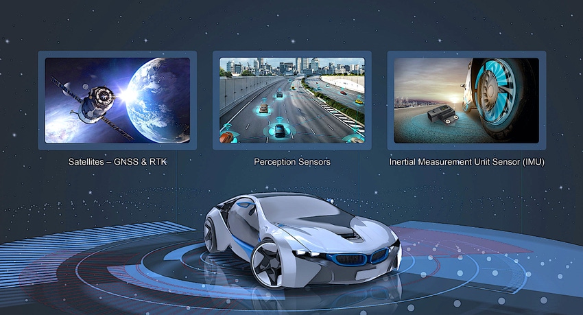
Although satellites cannot solely guide autonomous vehicles, they are vital contributors to the overall navigation process. The second pillar is composed of perception sensors, such as lidar, radar, and cameras. The third component is the Inertial Measurement Unit, or IMU
The Internal Measurement Unit – IMU
The unique value proposition of an IMU is its isolation. Perception sensors can be blocked by atmospheric conditions, including but not limited to heavy rain or snow. And any type of satellite transmission can be impeded or completely blocked by something as benign and ordinary as a tunnel or even the walls of a parking garage. However, the IMU is always available and is tasked with filling in the gaps between GNSS updates and during short GNSS outages.
As the name suggests, inertial measurement units are primarily tasked with measuring change in inertia. It does so in both linear and angular (rotational) dimensions.
|
IMUs and Linear Calculations
IMUs measure acceleration in all three dimensions. Integrating acceleration yields velocity, and integrating that result, velocity, yields distance traveled. In addition, the IMU can measure the Earth’s gravity vector and determine its orientation (attitude) using simple geometry. Thus, through an IMU, acceleration, velocity, relative position, and attitude can be measured or calculated.
IMUs and Angular Calculations
An astonishing technology, microelectromechanical systems (MEMS), makes it possible to “print” tiny mechanical devices, including accelerometers and gyroscopes, in the same manner as integrated circuits are built. Before the advent of MEMs, it wasn’t practical to build gyroscope-based subsystems into automobile sensors because of size and cost constraints.
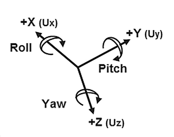
In addition to IMUs measuring 3D linear acceleration they also measure 3D angular (rotational) rate. Similar to integrating the linear acceleration, integrating angular rate over time will yield relative angle (pitch, roll and yaw).
Putting it all together - The INS Core
The INS Core, aka the Customized Extended Kalman filter, analyzes the reporting from the IMU, the satellite data and the information from the perception sensors. However, there may be disagreement between the satellite-based information, the IMU and the perception sensors.
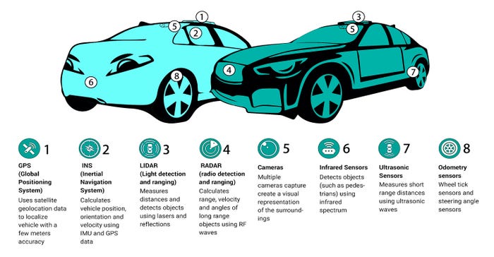
Here, the INS core must function like a baseball manager, who sidelines a player who is experiencing a slump, often the reporting element in greatest disagreement with its peers. The tactic is called sensor fusion.
Here is an example – all gyroscopes have a tendency to drift. This is called bias drift. Additionally, integration itself will generate errors over time. The noisier the gyro, the bigger the errors. As a result, the angle in each dimension calculated from the gyroscope data, gradually diverges from the true value. But, by measuring the Earth’s gravitational field with the linear acceleration sensors, the Sensor Fusion Engine has a pointer to the center of the earth. The INS Algorithm can then keep track of and remove errors from the attitude calculations from the gyroscope data. Similarly absolute position data from the GNSS / RTK positioning engine can be used to remove drift and integration errors from the IMU calculations of position and velocity.
IMUs are Autonomous, But…
This illustrates a central point. The IMU can continue to report and update attitude, position, and velocity even when GNSS or other perception sensors are denied or unavailable. That’s why IMUs are considered to be autonomous. However, because the gyroscope bias will drift without some reference to provide correction (like GNSS / RTK), its report is less accurate as a function of outage time.
Sensor Fusion
Accelerometers and gyroscopes are just one example of sensor fusions, where the measurement of the Earth’s gravitational field can help the INS Algorithm to error correct the gyroscopes bias and integration errors.
Another example is distance. Accelerometers measuring linear acceleration, double integrated to derive distance, can also drift. Once the GPS / GNSS signal is again available, location can be ascertained, and error correction can occur. The quality of the IMU will largely determine how long the vehicle can safely operate while deprived of satellite information.
Taking Polls
The central task of the INS Core is to ascertain which reading, or combination of readings are most correct. It must judge, as illustrated below, if the perception sensor(s), the GNSS data, or the gyroscopes give the best result. The process is diagrammed in the illustration below.
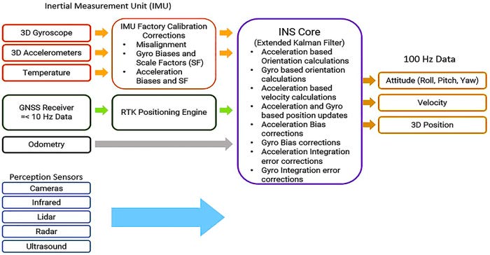
While multiple types of sensors are often used in sensor fusion, the same principles apply inside a single device such as the IMU383ZA wherein multiple data sets are combined and compared to provide more accurate information.
RTK faces some of the same challenges as does 5G – deployment of enough base stations to cover the entire continent. Devices such as ACEINNA RTK330LA are rapidly coming down to the price point where they will be affordable for passenger vehicles, but the absence of widely available RTK means that greater accuracy of inertial measurement units will be needed for totally autonomous vehicles.
|
James Fennelly is ACEINNA Inc.'s Product Marketing Manager – Inertial Systems. Fennelly received his BS EET from the University of Massachusetts. He has been working for the past 10 years with MEMS inertial sensors including component level acceleration sensors and system level products. He is responsible for defining new products at ACEINNA Inc. to meet the needs of emerging applications in the inertial sensing market.
You May Also Like
