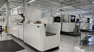
Mechanical conveying is a broad classification within the bulk material handling field.
February 15, 2022
Noel Wallace, bulk materials handling manager, Hatch
You might ask, what is mechanical conveying and what applications does it have? How does one select the right mode of mechanical conveying and how is it sized for an application? What sort of design process should be applied and does one size fit all?
This article focuses on distinguishing and describing various mechanical conveying equipment types, identifying the numerous industries and applications for mechanical conveying, and identifying design considerations for the development of mechanical conveying solutions.
Before addressing these topics, let’s define what mechanical conveying is and what applications it has. Mechanical conveying equipment is designed for moving bulk material from one location to another. This can either be for the purpose of transport or facilitating a process within a plant. For the purposes of this article, mechanical conveying modes are seen to be distinct from pneumatic conveying (fluidized material flow) and pumping (material converted to a slurry for transport).
Equipment Types
Typical bulk materials handling equipment that falls under the mechanical conveying classification includes:
* Belt (and pipe) conveyors
* Bucket elevators
* Flexible walled belt conveyors
* Drag chain conveyors
* Screw conveyors
* Vibratory conveyors
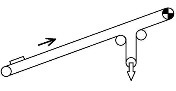
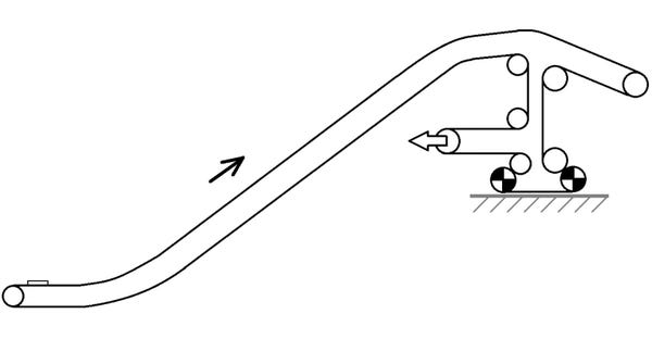
Another type of bulk material handling equipment typically integrated within mechanical conveying systems, but is not itself mechanical conveying, are feeders (vibratory, belt, apron, plough, etc). This type of bulk materials handling equipment acts as a means for activating or promoting flow or facilitating efficient transfer of material and uniform discharge of bins or hoppers. In every case, the interfaces/transfer between mechanical conveying elements and other bulk materials handling equipment requires careful consideration.
Within the field of bulk material handling, variations on the above main equipment types exist. For example, in the case of belt conveying, there exists a number of equipment designs that are based on cable technology and utilize specially constructed belting to support the material, while the cable takes the tension loading. Examples of these include cable-belt and RopeCon. Another form of specialized conveying is based upon individual small railcars connected on a dedicated track that are moved using either cables or chains. Due to their unique design, they require tailored transfer arrangements.
Industries and Applications
Industries that require the implementation of mechanical conveying include mining, mineral processing, iron making/pyrometallurgy, hydrometallurgy, energy (power plants, including biomass), ports and marine, and supply chain (transport).
Within these industries, the implementation of mechanical conveying breaks down into two fundamental applications: in-plant (process) or overland (transport).
1. Process or In-Plant Applications
These applications are the most used and typically operate within the boundaries of a plant and serve a specific function. The most common function is transferring material from one location to another within the plant. Further, stacking and reclaiming functions are fulfilled by mechanical conveying. Delivering raw material to the inlet of the main process or receiving the product produced by the process plant, are other important functions. Examples include delivery of coal to a power plant bunker, feeding of material to a furnace, or transferring of material into crushing and sizing equipment. Some processes require a consistent feed rate (tph) and particle size (mm). Depending upon the process, the mechanical conveying mode may need to be acute with tight set-point control available, as it may operate as a metering device such as in the case of reliable feed to a furnace inlet or within a mineral processing plant.
Additionally, modes of mechanical conveying function as the interface between the plant and the outside world. They receive material from unloading facilities and deliver to stockpile areas within the plant or to load-out facilities for transport or export. The unloading and loading facilities can be conveyor, truck, rail, or ship.
In general, in-plant mechanical conveying equipment is relatively short (up to 1,000 m long for belt conveyors) and is straight in plain view (but can be vertically curved). Typically for in-plant belt conveyors, a static analysis is sufficient to determine their required sizing.
2. Transport (overland)
Transport applications are typically much longer (more than 1,000 m long) and can relate to the supply chain industry or represent an alternative mode of transport to trucking and/or rail. Accordingly, these types of applications are usually serviced by either belt or pipe conveying as bucket elevator, flex-walled conveyors, drag, and screw conveyors are not capable of such lengths.
Typically, transport applications connect one geographically remote location to another and can traverse harder to navigate terrain through elevated sections and tunnels. Further, the profile of overland conveyors can be both vertically and horizontally cured resulting in significantly more complex conveying geometry. Accordingly, these types of conveyors require more evaluation than in-plant mechanical conveying and are usually subject to dynamic analysis.
These types of overland conveyors are capable of much higher capacity (tph) – typically in the thousands of tons per hour – which makes them commercially viable for trucking and rail transport.
Selection and Sizing
The sizing and/or selection of mechanical conveying equipment depends on the specific operating parameters of the application. Depending on the material being handled, the governing factor(s) may be different from application to application.
Typically, the main metrics that a mechanical conveying application is based on includes (but may not be limited to) the following:
* Material properties*
* Capacity (tn/hr, lb/min)
* Bulk density (kg/cu m, lb/cu ft)
* Maximum lump and particle size distribution (mm/in.)
* Surcharge angle/angle of repose (deg)
* Temperature (°C/°F)
* Moisture (%)
*Material properties can vary. When not available from clients, laboratory testing of indicative samples can be carried out. The typical material properties that are analyzed include flowability, particle shape, size, density, tendency to break-down and generate fines or dust, tendency to separate into smaller and larger particles, agglomerating (clumping) properties, fluidization properties (ability to aerate and become “liquid-like”) and wear effects against various material liners.
The following items must be considered when developing a mechanical conveying system:
* Environmental concerns (dust, spillage, hygiene, etc.)
* Available real estate
* Geometry
* Required conveying angle
Belt (and pipe) conveyors need to be engineered from first principles engineering design and development. No two applications are the same and dedicated calculations must be performed for each one (depending upon the specific design of a plant, “twin” conveyors may be appropriate). Well-established calculation methods, supported by industry accepted design software, are performed and specific sizing of the conveyor is established. The first step in the design process is understanding the required operating parameters and applying the design software to size the required componentry. In the case of belt (and pipe) conveyors, once power and tension calculations are completed, further detailing can be executed to size and select specific componentry such as belting, idlers, pulleys, and drive units.
While belt conveyors are calculated using established methods, other mechanical conveying equipment is usually size-based on design requirements and correlated with specific catalogue data. Operational requirements are assessed, and performance specifications are developed. Subsequently, look-up tables (with specific model numbers) are used to select the correctly sized conveyor. To compile the catalogue information, sizing calculations have previously been performed or the data is derived from empirical evidence. Examples of this classification of equipment are drag chain conveyors and screw conveyors. These can be described as “off-the-shelf engineered items” meaning their sizing is available in catalogues and have specific model numbers relating to defined performance requirements. Bespoke solutions are sometimes available, but typically, required sizing must be determined before selecting the most appropriate item from a pre-existing catalogue.
Typical Design Constraints or Governing Factors and How They Are Overcome
Please note, this is not an exhaustive list and only covers common situations for mechanical conveying applications. As with all bulk materials handling applications, best engineering practice should be applied from first principles:
* Distance
* Throughput (tn/hr)
* Function/required operation
* Limited real estate
* Limit dust and/or spillage (e.g. over water/near residential area)
* Process – metered flow (coupled with an outlet valve)
Combination of Different Mechanical Conveying Equipment
In a typical plant, to overcome the above listed design constraints, it is common to combine multiple modes of mechanical conveying to fulfil a dedicated process. For example, belt or pipe conveyors can be used to transport raw material from an unloading facility to the plant and stockpile area. Reclaimed material can be directed to a process plant via more belt conveyors. If real estate is limited and significant vertical heights need to be traversed, a bucket elevator or flexible walled conveyor can be used, dependent upon required throughput (tph). Once material is sized and lower throughputs are required, drag chain and/or screw conveyors can be utilized to meter material into process equipment in a controlled manner.
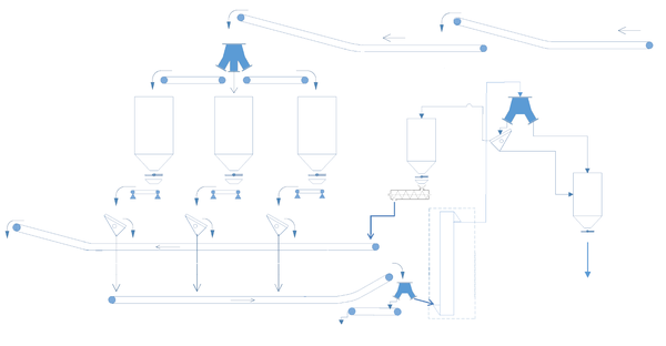
Mechanical Conveying Systems
With regard to mechanical conveying application, each application is unique, and the first step should be a review/analysis of required operation. A one-size-fits-all mindset should not be employed, and consideration should be given for maintenance requirements and access around the equipment.
All engineering constraints and governing factors must be identified and factored into the design from the earliest conceptual phase to ensure correct selection of mechanical conveying equipment. Subsequently, equipment sizing and selection must be implemented using industry accepted methods and tools.
Within any given plant, multiple types of mechanical conveying are used, and the selection of the correct mechanical conveying equipment is paramount. Integration of the separate bulk material handling elements and wrap around engineering is required for a seamless mechanical conveying system to be developed.
With any mechanical conveying application, exceptional engineering experience with all bulk materials handling elements is necessary.
Noel Wallace is bulk materials handling manager, Hatch (Mississauga, ON, Canada). For more information, call 905-403-4004 or visit www.hatch.com.
You May Also Like


