August 30, 2011

There is a current trend and an increasing number of requests for designing brushless DC motors into high-speed applications. New impeller technology, for instance, is changing the way modern respirators are designed, allowing them to be more compact and quieter. Such performance requires motors that rotate up to 50krpm to 60krpm and are capable of delivering high acceleration and deceleration in synchrony with a patient's breathing pattern. Other examples include surgical and dental hand tools where motors have to be ever stronger and smaller.
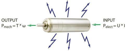
One way to achieve this level of performance is to use high-speed brushless motors that can deliver the necessary power and performance, within the preferred footprint. Mechanical power is the product of torque and speed, and, to increase power, there is a need to either increase torque or speed. But generally, for a given technology, continuous torque is related to the motor's size and is often limited by thermal considerations.
Without considering high-speed constraints, a motor designer will try to optimize the torque the motor can dissipate for a given power dissipated by Joule effect. The figure of merits R/k 2 is a good factor to characterize a motor, and a good motor should have a small resistance and a high torque constant. One way to increase the torque constant is to use stronger magnets such as NeoFe.
In order to decrease Joule losses, the objective is to have as large a wire section as possible, to create the lowest copper resistance. After optimization of R/k 2, maximum torque is still limited for a given motor size by its thermal limitation. Consequently, the other parameter to increase the power is to increase the speed.

In theory, it seems easy to increase the speed by simply increasing the voltage of the power supply. However, increasing speed will generate more heat due to iron losses, bearing friction losses, and current ripple that also creates losses.
Iron losses due to Eddy current are the losses generated by the current circulating in the lamination created by magnetic flux. To decrease these losses, thinner laminations with high electrical resistance are used to increase the resistance within the lamination.
The magnetic material used to conduct the magnetic field also produces losses due to hysteresis. Every time the magnetic flux is reversed, the hysteresis of the material will generate losses. During the design, engineers can optimize hysteresis losses by using specific magnet materials such as FeNi.
Iron losses depend on the square of the induction in the iron laminations, and on the square of the frequency. For this reason, motors generally having a high number of pole-pairs will have speed limitations. In many cases, according to the specific design, a motor with two pole-pairs will have more iron losses than a motor having one pole pair, but it's likely this motor will have a better R/k 2.
About the Author(s)
You May Also Like


