January 24, 2014

A step motor is an open-loop, brushless, digital actuator driven in fixed angular steps.
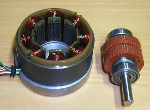
The hybrid step motor is most common and has magnetically permeable teeth on both the stator and rotor. The sources of magnetic flux are the stator windings and the rotor permanent magnet (which gives it a detent torque when not energized); high magnetic flux leads to high tangential forces between rotor and stator teeth, resulting in high torque. There are two stator windings, each situated on alternating poles; successive poles of each winding are wound in the opposite sense.
Hybrid motors have four phases: a bipolar (unifilar) motor uses current reversal in each winding, while a unipolar (bifilar) motor uses twice the number of windings. The step angle is 90 degrees divided by the number of rotor teeth, with 1.8 degrees most common; four phase excitations (four steps) correspond to one rotor-tooth pitch. For a well-designed step motor, the stator/rotor iron should reach magnetic saturation at the rated winding current. A step-motor system is a mechatronic system and its performance is determined by the motor, the motor driver, the load connected to the motor, and the desired motion trajectory.

In a hybrid step motor, torque is linearly proportional (constant kT) to the phase current. The data-sheet holding torque TH is usually obtained with two phases energized at the rated current Ir. The motor torque constant kT for one coil is obtained by dividing TH by (1.414)Ir, since TH results from the vector sum of torques from each phase.
Resistance (R) and inductance (L) are the two inherent physical characteristics of a step-motor winding, and these limit the possible performance of the step motor. R is responsible for the major share of the power loss and temperature rise of the motor. L makes the motor winding oppose current changes and therefore limits high-speed operation. To drive current through a winding, use as high a voltage as possible and keep the inductance low.
The driver circuit has two major tasks: (a) change the current and flux direction in the phase windings, and (b) drive a controllable amount of current through the windings enabling as short current rise and fall times as possible for good high-speed performance. The chopper driver provides an optimal solution both to current control and fast current build-up and reversal. Use a supply voltage several times higher than the nominal voltage of the motor; the current rise rate will increase substantially. Control the duty cycle of the chopper, using a current-sensing resistor, to achieve constant current regulation. This results in precise control of the developed torque and minimizes power dissipation.

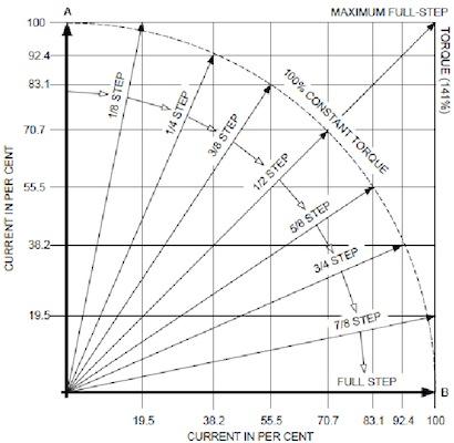
Step motors can be driven in several modes: full-step, half-step, or micro-step (quarter and eighth stepping are common). Full-step operation can be achieved by one-phase-on excitation at a time at the rated current. Maximum torque is achieved in the full-step mode with both phases fully energized at the same time for each step.
Step motors are everywhere and are just one component in an integrated system. Fundamental understanding is essential.
Related posts:
About the Author(s)
You May Also Like


