Sign up for the Design News Daily newsletter.
3D printing is a new way to get a physical example of flow simulation results to vividly observe pressure, temperature, and velocity parameters.
January 29, 2016
4 Min Read
.svg?width=850&auto=webp&quality=95&format=jpg&disable=upscale "Another Use for 3D Printing: Physically Modeling Fluid Flow Trajectory Lines")
Computational fluid dynamics (CFD) software is widely used by the mechanical engineering community to determine fluid flow. The most important information is typically how variables such as density, velocity, and temperature change as the fluid flows inside or around a structure.
3D printing allows the creation of models that brilliantly display flow simulations that can be used for product demonstrations or at trade shows to describe designs more vividly. The lines in the model depict the flow of fluids, and different colors indicate changes to key variables.
Figure 1 shows a CAD model of a globe valve. The left side has an inlet with mass flow rate defined and the right side indicates atmospheric pressure.

Figure 1: CAD model of a globe valve.
(Source: GoEngineer)
Flow trajectory data are analyzed using images and animations within the CFD software. In Figure 2, the flow of water is analyzed and the trajectory lines for velocity distribution are displayed. The range of colors between blue and red represents slower to faster velocities.
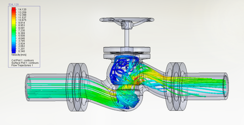
Figure 2: Flow trajectories showing velocity inside a globe valve.
(Source: GoEngineer)
SolidWorks Flow Simulation can export the trajectory lines as curves that can be used to create solid bodies. To represent multiple colors, a single curve might entail four or five different solid bodies, since each solid body must be a unique color (Figure 3). The fluid volume can also be exported as a separate solid body. This body represents the entire space inside the structure where the fluid can flow.
[Visit SolidWorks at booths 3401 at Pacific Design & Manufacturing, Feb. 9-11, at the Anaheim Convention Center.]
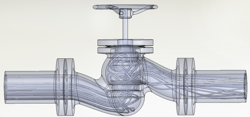
Figure 3: CAD model showing solid bodies of flow trajectory lines.
(Source: GoEngineer)
The volume occupied by the solid bodies representing the flow trajectories is subtracted from the fluid volume to ensure there is no overlap. This completes the creation of the structural geometry; its trajectories are ready for 3D printing. (The assembly file is saved in STL format.)
[Visit Stratasys at booths 3601 and 3605 at Pacific Design & Manufacturing, Feb. 9-11, at the Anaheim Convention Center.]
A Stratasys Connex3 printer is used to additively manufacture the 3D model in Figure 4 in approximately 18 hours. The Connex3 uses PolyJet technology, which can print in the widest variety of materials. PolyJet 3D printing is similar to inkjet printing, but instead of jetting ink onto paper, it jets layers of curable liquid photopolymer onto a build tray.
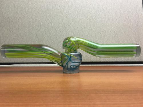
Figure 4: 3D-Printed flow model showing trajectory lines of a globe valve.
(Source: GoEngineer)
The Connex3 printer has the ability to print three colors or any mixture of the three colors. Figure 5 shows the palette. The three colors used in this example are Vero Clear, Vero Yellow, and Vero Blue. The engineer assigns colors for each of the solid bodies from this palette.
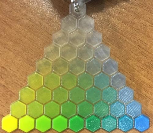
Figure 5: Palette used for 3D printing the flow trajectories shown in Figure 4.
(Source: GoEngineer)
Creating a CAD model with solid bodies is an elaborate process. However, the end result is a transparent 3D-printed part that shows, with easily distinguishable colors, the details of how fluid flows inside a given geometry or around it.
READ MORE 3D PRINTING ARTICLES ON DESIGN NEWS:
3D printed models of flow trajectories are more likely to be used for sales and marketing purposes. However, the value to the product development process should not be overlooked. When everyone on the team can see a physical example of the problem they are trying to solve, it often generates new ideas and approaches to solve the problem at hand.
Similar 3D prints may also serve as engineering or educational models for the classroom. The medical community already uses 3D printing to make anatomical models for learning.
Manufacturing applications engineer Arvind Krishnan works at GoEngineer, focusing on finite element analysis and 3D printing. He completed his master’s degree in mechanical engineering at North Carolina State University with a thesis in Using Michell Truss Principles to find an Optimal Structure Suitable for Additive Manufacturing. Arvind enjoys playing tennis, badminton, racquetball, chess, and soccer; he is also passionate about hiking and cooking.
Like reading Design News? Then have our content delivered to your inbox every day by registering with DesignNews.com and signing up for Design News Daily plus our other e-newsletters. Register here!
You May Also Like
Editors' Choice


Jun 4 - Jun 6, 2024
Jun 4 - Jun 6, 2024
Innovation in automation starts here. Discover and collaborate on automation solutions that are revolutionizing the entire production lifecycle — from design to production to market — and sharpen your competitive edge. ATX South is part of IME South, a six-in-one expo offering the latest insights & solutions spanning medtech, packaging, automation, plastics, design, & processing.
Register Now