InkBot: Building Your Own Robot That Writes
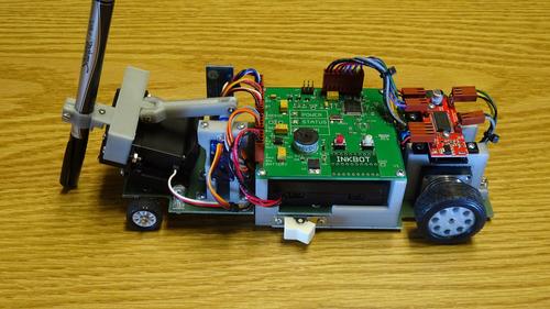
Kerry Erendson wanted to create a DIY robot that could write. The result was InkBot. Kerry shares the process of designing and building InkBot and shows you how to build your own.
May 20, 2016

Seeing all of the YouTube videos of robotic arms that write on dry-erase boards I knew I'd have to a make one of these my next project. Since I’m really into cars I thought, what better approach than a car-like robot that writes on paper as it travels? This project is about 50% 3D-printing/mechanical and about 50% electronics/software. I've been an electronic design engineer for 35 years, but I only got into 3D printing about a year ago. I love projects that combine both.
My basic concept is that the X-axis pen motion will be the vehicle's motion forward or backward. The Y-axis travel will be provided by a linear servo motor. The Z-axis is the pen height, driven by the small blue servo motor through the 3D-printed arm with a clevis at each end: Down = tip touching the paper to write; Up = tip lifted slightly from the paper; Lift = pen lifted into a park position which allows room for the pen cap to be put back on.
Overall Assembly Parts List |
InkBot PCB (3.3" x 3.0" double sided), assembled, see PCB parts list in full instructions |
Wiring Harness (see document " InkBot Chassis Wiring Diagram.pdf" in full instructions) |
Bluetooth Module JY-MCU from dx.com or other source |
Large Servo for Y-axis Futaba S3003 with EMS Linear Servo conversion kit installed |
Power Switch, mounts in chassis |
Battery Pack (holds 4 AA batteries) |
Easy Driver stepper motor driver buildd, based on Allegro A3967 |
Stepper Motor NEMA11 Bipolar Dual-shaft 1.8deg/step |
3D printed parts, 13 pieces / 11 designs, see SketchUp files including in full instructions |
.062" fiberglass sheet, as required, see outline drawings in full instructions |
Wheels / axel, see description in main write-up above |
Various sheet metal & machine screws, |
And click here to download the full build instructions for InkBot along with complete schematics and diagrams, firmware, and 3D printer design files.
I started development by shopping for a stepper motor with dual shafts. Given that, I could just put wheels directly on the shafts and take advantage of the fact that I only want the robot to go forward and backward, as straight as possible. I based it all on the geometry of a 32 x 32 line-segment character font, approx. 0.65 square inch, with the X-axis figure inclusive of the space between characters.
I calculated the wheel diameter to make each of the 1.8˚ steps draw a very short line in the X-axis, 1/32 of the allowed character width. The wheel diameter in turn established the limit on the stepper motor size, which led me to the NEMA 11 form factor. With a 1.1 square inch stepper motor mounted directly to .062-inch fiberglass sheet, using the target wheel size, there would still be (a very small amount of) ground clearance.
Do you have a cool, original, homemade gadget collecting dust in your garage? Give us the details at designnews.com/gadget-freak-entry-form, and you may receive $500 and automatic entry into our $6000 Gadget Freak of the Year contest!
[All images courtesy Kerry Erendson]
About the Author(s)
You May Also Like
.jpg?width=300&auto=webp&quality=80&disable=upscale)


