Motors, Actuators, Conveyors
spaced-based robot surgeon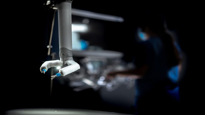
IndustrySurgical Robot Heads for Space and Supplier NewsSurgical Robot Heads for Space and Supplier News
We’re also checking out low-voltage servo systems, capacitive level sensors, and surface-mount devices.


.jpg")


Editors' Choice


Jun 4 - Jun 6, 2024
Jun 4 - Jun 6, 2024
Innovation in automation starts here. Discover and collaborate on automation solutions that are revolutionizing the entire production lifecycle — from design to production to market — and sharpen your competitive edge. ATX South is part of IME South, a six-in-one expo offering the latest insights & solutions spanning medtech, packaging, automation, plastics, design, & processing.
Register NowSign up for the Design News Daily newsletter.